
Optical Aberrations
Interactive Tutorials
Spherical Aberration
The most serious of the classical Seidel monochromatic lens aberrations that occurs with microscope objectives, spherical aberration, causes the specimen image to appear hazy or blurred and slightly out of focus. Ideally, an aberration-free objective converts a plane wavefront into a spherical wavefront, directing all light waves refracted by the lens to a common focal point in the center of the sphere to produce a perfect image.
The effect of spherical aberration manifests itself in two ways: the center of the image remains more in focus than the edges, and the intensity of the edges falls relative to that of the center. This defect appears in both on-axis and off-axis image points.
The tutorial initializes with an image of the specimen (as seen through the microscope) appearing in a window on the left-hand side of the applet. Beneath the image window is a pull-down menu labeled Choose A Specimen, used to select a new specimen. The Lens Shape slider is designed to control the tutorial by introducing an increasing amount of spherical aberration into the optical system. Moving the slider to the right also induces changes corresponding to the introduction of spherical aberration into the Airy diffraction pattern shown in the center of the applet window. Simultaneously, intensity is shifted away from the central peak of the point spread function and into the surrounding rings, which become far more prominent. These changes are also correlated with the ray trace diagram presented in the right-hand side of the applet.
Spherical aberration artifacts are encountered when light waves passing through the periphery of an uncorrected convex lens are not brought into focus with those passing through the center. Waves passing near the center of the lens are refracted only slightly, whereas waves passing near the periphery are refracted to a greater degree, producing a variety of different focal points along the optical axis. As a result, the peripheral waves come to a shorter focus (nearer the back of the lens or objective) than do rays traveling through the central or axial area. This is known as longitudinal or axial spherical aberration. Axial aberration is generated by non-spherical wavefronts produced by the objective itself or by improper use of the objective. Some of the most common causes are failure to maintain the designated microscope tube length or the presence of substances between the objective and focal plane having a spurious refractive index.
What is seen in the microscope is an image made by focusing the peripheral rays surrounded by the unfocused image of rays traveling through the central portion of the lens (or visa versa). This is one of the most serious resolution artifacts because the image of the specimen is spread out rather than being in sharp focus. The best focus, in an imperfectly or non-corrected lens, will be somewhere between the focal planes of the peripheral and axial rays, an area known as the disc of least confusion (illustrated as a point on the optical axis in the tutorial figure). Light rays refracted by the rim of the lens or pupil (peripheral rays) have the shortest focal length and produce the smallest image, whereas those that intersect at the paraxial focal point (axial rays) have begun to spread and do not represent the "best" focus.
Only when the specimen and image distances can be accurately specified can spherical aberration be optimally corrected. This artifact can be easily introduced by improper tube length caused by introduction of optical elements into the converging beam path of finite tube length microscopes. Spherical aberration can also occur when using improper "windows", such as cover glasses of nonstandard thickness (deviations from 0.17 millimeters) or poor quality immersion oil between the objective front lens and the cover glass.
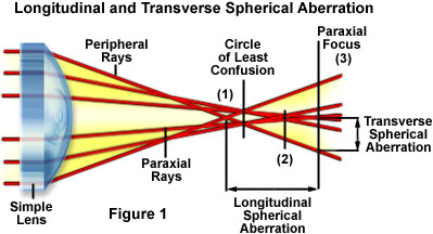
The tutorial illustrates an exaggerated view of three hypothetical monochromatic light rays passing through a convex lens and converging on a series of focal points that lie in a progression along the optical axis (see the Ray Trace Diagram). Changes to the shape of the lens with corresponding adjustments to the focal point position(s) can be made by utilizing the Lens Shape slider. Refraction of peripheral rays at the edge of the lens is greatest followed by those in the middle and then the rays in the center. The larger refraction by the outermost rays results in a focal point (focal point 1; see Figure 1) that occurs in front of the disc of least confusion and the focal points produced by rays passing closer to the center of the lens (focal points 2 in the center and 3, at the paraxial focal plane; Figure 1). Also illustrated in Figure 1 is a measure of the transverse spherical aberration, defined as the distance from the optical axis at which the peripheral rays intersect the plane of paraxial focus. As is evident in the figure, transverse aberration is measured in the plane of the image and is useful as an indicator of image blur.
Most of the discrepancy in focal points arises from approximations of the equivalency of sine and tangent values of respective angles made to the Gaussian lens equation for a spherical refracting surface:
where n and n' represent the refractive index of air and the glass comprising the lens, respectively, s and s' are the object and image distance, and r is the radius of curvature of the lens. This expression determines the relative locations of images formed by the curved surface of a lens having radius r sandwiched between media of refractive indices n and n'. A refinement of this equation is often referred to as a higher-order (first, second, or third) correction by including terms in the cube of the aperture angle, resulting in a more refined calculation. Departure from an ideal spherical wave is expressed in terms of fractions of a wave, where a single wave is equal to the average wavelength of the illuminating light. This deviation is termed the optical path difference, which must be less than one-quarter wavelength before a diffraction limited objective can be considered aberration-free.
As the objective numerical aperture is increased, changes in cover glass thickness or refractive index become critical, particularly with high magnification dry objectives where small changes in tube length quickly lead to inferior images. Although spherical aberration can be corrected to almost undetectable limits for visual observation with all types of objectives, the optical specification for any given lens must be fulfilled. For oil-immersion objectives having high numerical apertures, this usually means using a cover glass having a 0.17 millimeter thickness and immersion oil with a refractive index of 1.5180 (± 0.0004) at wavelengths of 546 and 589 nanometers. Complicating these conditions is the fact that for almost all materials, refractive index is a function of both wavelength and temperature. In cases where the exact properties of the cover glass and oil are specified, microscope manufacturers can correct spherical aberration for several values of wavelength.
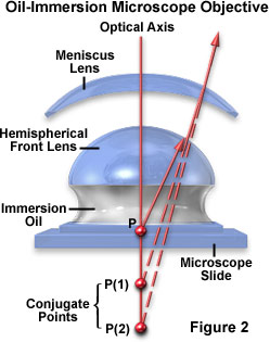
One of the mechanisms used to eliminate spherical aberration in oil immersion objectives is to design the optics around specific pairs of conjugate points using a hemispherical and meniscus lens at the front of the objective. As illustrated in Figure 2, for a specimen observed at position P and surrounded by immersion oil of refractive index n, there exists a conjugate point (P(1)) to eliminate spherical aberration in the first lens element (the hemispherical lens). In this case, light rays emanating from point P leave the surface of the hemispherical front lens as if they originated at point P(1). The meniscus lens is ground with a surface radius centered on point P to form a second conjugate pair (P(1) and P(2)). Thus, light from the specimen a point P ultimately exits the meniscus lens as if it originated at point P(2), eliminating spherical aberration for the lens combination.
Specimens mounted in Canada balsam or similar mounting media that have a refractive index approximating that of the cover glass are not prone to spherical aberration errors. However, this is not true for specimens mounted in physiological saline or other aqueous media with refractive indices significantly different from the cover glass. Even when focusing through thin layers of water only a few microns thick, significant aberrations are encountered that can induce dramatic asymmetries into the point spread function causing a non-uniform distribution above and below the focal plane. This concept is explored in the interactive tutorial linked below.
| Interactive Java Tutorial | |||||||||||
|
|||||||||||
Spherical aberrations are very important in terms of the resolution of the lens because they affect the coincident imaging of points along the optical axis and degrade the performance of the lens, which will seriously affect specimen sharpness and clarity. These lens defects can be reduced by limiting the outer edges of the lens from exposure to light using diaphragms and also by utilizing aspherical lens surfaces within the system. However, a consequence of reducing aperture size in the microscope optical system is a concurrent reduction in the amount of light entering the system. Spherical aberration is usually corrected by employing glass elements (lens doublets or triplets) cemented together. The glass elements are designed with different shapes of convexity and/or concavity to insure that the peripheral rays and axial rays, especially at the outer area of the field of view, are brought into common focus.
Until recent years, achromats were corrected spherically only for green light, although they were corrected chromatically for two wavelengths. Also, apochromats were corrected spherically for two wavelengths, blue and green, but were corrected chromatically for three wavelengths. The highest-quality modern microscope objectives address spherical aberrations in a number of ways including special lens-grinding techniques, improved glass formulations, and better control of optical pathways through use of multiple-lens elements. Currently, the highest quality objectives, planapochromats, are spherically corrected for four wavelengths, as are planfluorites (but not to quite as close a tolerance).
| Interactive Java Tutorial | |||||||||||
|
|||||||||||
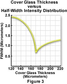
It is also possible for a user to inadvertently introduce spherical aberration into a well-corrected system. For example, when using high magnification, high numerical aperture dry objectives, the correct thickness of the cover glass (suggested to be 0.17 millimeters) is critical. Figure 3 illustrates the changes in half-width of the intensity distribution curve with changes in cover glass thickness. Even with high quality cover glasses having a tolerance of ±10 micrometers, the half-width changes by more than a factor of two. As the objective numerical aperture is increased (above a value of 0.5), particularly with dry and water immersion lenses, selection of cover glasses for the correct thickness is particularly important.
High-quality oil immersion objectives perform optimally only when they are used with a cover glass thickness of 0.17 millimeters. To help alleviate cover glass variations, correction collars are often included on dry objectives to enable adjustment of intermediate lens elements to compensate for deviant cover glass thickness. Because focus may shift and the image may wonder during adjustment of the correction collar, the utilization of correction collars demands that the microscopist remain alert in order to reset the collar using appropriate image criteria. In addition, the insertion of accessories in the light path of finite tube length objectives may introduce aberrations, when the specimen is refocused, unless these accessories have been properly designed with additional optics.
Contributing Authors
H. Ernst Keller - Carl Zeiss Inc., One Zeiss Dr., Thornwood, NY, 10594.
Kenneth R. Spring - Scientific Consultant, Lusby, Maryland, 20657.
John C. Long and Michael W. Davidson - National High Magnetic Field Laboratory, 1800 East Paul Dirac Dr., The Florida State University, Tallahassee, Florida, 32310.
BACK TO LENSES AND GEOMETRICAL OPTICS