
Optical Aberrations
Interactive Tutorials
Astigmatism
Astigmatism aberrations are similar to comatic aberrations, however these artifacts are not as sensitive to aperture size and depend more strongly on the oblique angle of the light beam. The aberration is manifested by the off-axis image of a specimen point appearing as a line or ellipse instead of a point. Depending on the angle of the off-axis rays entering the lens, the line image may be oriented in either of two different directions, tangentially (meridionally) or sagittally (equatorially). The intensity ratio of the unit image will diminish, with definition, detail, and contrast being lost as the distance from the center is increased.
The tutorial initializes with a fluorescence photomicrograph of a bovine pulmonary arterial cell appearing in the window on the left-hand side of the applet. The cell is triple-stained with DAPI, BODIPY, and MitoTracker Red CMXRos. Beneath the image window is a pull-down menu labeled Choose A Specimen, which can be used to select a new specimen from the palette. The Off-Axis Distance slider is utilized to control the tutorial by introducing an increasing amount of astigmatism into the optical system. Moving the slider to the right emphasizes the tangential plane, while moving the slider to the left illustrates the effects occurring in the sagittal plane. As the slider is moved to the left or right, the microscope image morphs to demonstrate an exaggerated view of how astigmatism will appear through the eyepieces (blurring horizontal lines while sharpening vertical lines and visa versa). Simultaneously, the point spread function and Airy patterns (shown in the central portion of the applet window) also change to simulate introduction of astigmatism. A four-lobed Airy pattern results when the focus is set at the compromise position between the sagittal and tangential extremes. Increasing the degree of astigmatism in the virtual optical system is also correlated with a ray trace diagram presented in the right-hand side of the applet.
Astigmatism aberrations are found at the outer portions of the field of view in uncorrected lenses, and cause the ideal circular point image (Airy pattern) to blur into a diffuse circle, elliptical patch, or line, depending upon the location of the focal plane. Illustrated in Figure 1 are off-axis light rays passing through the tangential and sagittal planes, which are collectively used to define the geometry of astigmatism. The tangential plane (also called the meridional plane) contains the chief ray and the optical axis of the lens (or lens system), while the sagittal plane (also called the radial and/or equitorial plane) contains only the chief ray and is positioned perpendicular to the tangential plane. The chief ray is defined as a special ray emanating from an off-axis point light source that passes through the center of the lens entrance pupil. In an optical system that is aberration-free, the chief ray will also pass through the center of the aperture diaphragm and the exit pupil of the lens.
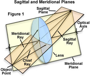
When considering a complex multi-element lens system, such as a microscope objective, the tangential plane is coherent from one end of the system to the other. In contrast, the sagittal plane usually changes slope as the chief ray is deviated by the elements composing the lens system, which often results in a sequential series of varying sagittal planes for each region of the system. A light ray bundle associated with either the sagittal or tangential plane will have a different configuration, resulting in different focal lengths for each plane. This discrepancy in focal length is a measure of the astigmatism, often referred to as the astigmatic difference, and will depend on the inclination angle of the light rays and the lens power (as opposed to the shape or refractive index). As an object (or specimen) light source point moves farther off-axis, ray fluxes enter the optical system at increasingly oblique angles, resulting in larger focal length differences.
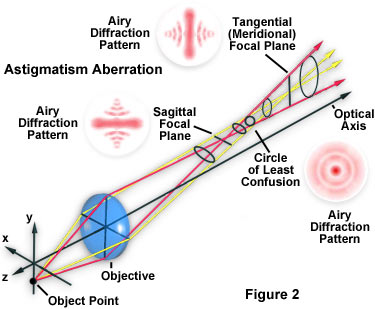
Light rays lying in the tangential and sagittal planes are refracted differently and both sets of rays intersect the chief ray at different image points, termed the tangential line image (tangential focal plane) and the sagittal line image (sagittal focal plane; see Figure 2). These rays fail to produce a focused image point, but rather produce a series of elongated images ranging from linear to elliptical, depending upon the position within the optical train. In a zone known as the circle of least confusion, positioned between the tangential line image and the sagittal line image, the major and minor axes of the ellipse are equal and the image approaches a circular geometry. These concepts are illustrated in Figure 2, which presents the principal axes of the tangential and sagittal light rays, the circle of least confusion, and shows approximate Airy patterns at strategic locations in the pathway.
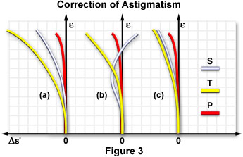
Every lens system has an inherent curvature, termed the Petzval curvature, associated with the refractive index of the component lens elements and their surface curvatures. Systems lacking astigmatic aberration have sagittal and tangential image surfaces that coincide with each other and lie on the Petzval surface. Astigmatism is often characterized by a dependence of the angle between the chief ray and the optical axis of the lens system, referred to as the field angle (e). Lens correction for astigmatism is generally represented by a plot of parabolic curves, which represents the position of the tangential (T; Figure 3) and sagittal (S; Figure 3) image points as a function of the field angle (e). An uncorrected lens displays a typical curve as shown in Figure 3(a), while several plots of lenses corrected for astigmatism are illustrated in Figure 3(b) and 3(c). Astigmatism represents the departure between the tangential and sagittal field curves (Figure 3(a)) with respect to the Petzval surface.
When astigmatism is present in a lens system, the tangential field departure from the Petzval surface is three times larger than that displayed by the sagittal field. If both the tangential and sagittal images are positioned to the left of the Petzval surface (Figure 3(a)), the astigmatism is called negative, undercorrected, or inward-curving (toward the lens). When this order is reversed, astigmatism is overcorrected or backward-curving. Negative lenses introduce backward curvature into an astigmatic lens system, whereas positive lenses produce inward curvature of the Petzval surface. In a thin-lens system, the longitudinal departure of a Petzval surface from an ideal flat image surface is equal to one-half the square of the image height divided by the focal length plus the refractive index of the lens element. In order to correct for astigmatism, it is necessary to reduce the value of the astigmatic difference, or the distance between the tangential and sagittal line images. Complete removal of astigmatism is difficult, but can occur in optical systems when the two curves, S and T, become flatter and coincide (Figure 3(c)), and the image is then formed in a region near the Petzval surface (P).
Poor lens centration in the objective or poor alignment between the objective, the intermediate optics, and the eyepiece increases astigmatism as it does coma. When a lens system is mis-assembled, astigmatism is severely affected, usually producing asymmetrical performance over the entire image area. Small tilt angles, even as low as 5 minutes of arc, are serious and lead to image degradation. Astigmatism errors are usually corrected by design of the objectives to provide precise spacing of individual lens elements as well as appropriate lens shapes, aperture sizes, and indices of refraction. The correction of astigmatism is often accomplished in conjunction with the correction of field curvature aberrations.
Contributing Authors
H. Ernst Keller - Carl Zeiss Inc., One Zeiss Dr., Thornwood, NY, 10594.
Kenneth R. Spring - Scientific Consultant, Lusby, Maryland, 20657.
John C. Long and Michael W. Davidson - National High Magnetic Field Laboratory, 1800 East Paul Dirac Dr., The Florida State University, Tallahassee, Florida, 32310.
BACK TO LENSES AND GEOMETRICAL OPTICS