
Concepts in Digital Imaging Technology
Photomultiplier Tubes
A photomultiplier tube, useful for light detection of very weak signals, is a photoemissive device in which the absorption of a photon results in the emission of an electron. These detectors work by amplifying the electrons generated by a photocathode exposed to a photon flux.
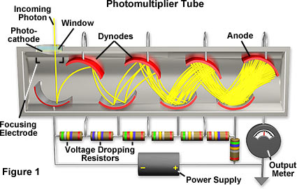
Photomultipliers acquire light through a glass or quartz window that covers a photosensitive surface, called a photocathode, which then releases electrons that are multiplied by electrodes known as metal channel dynodes. At the end of the dynode chain is an anode or collection electrode. Over a very large range, the current flowing from the anode to ground is directly proportional to the photoelectron flux generated by the photocathode.
The spectral response, quantum efficiency, sensitivity, and dark current of a photomultiplier tube are determined by the composition of the photocathode. The best photocathodes capable of responding to visible light are less than 30 percent quantum efficient, meaning that 70 percent of the photons impacting on the photocathode do not produce a photoelectron and are therefore not detected. Photocathode thickness is an important variable that must be monitored to ensure the proper response from absorbed photons. If the photocathode is too thick, more photons will be absorbed but fewer electrons will be emitted from the back surface, but if it is too thin, too many photons will pass through without being absorbed. The photomultiplier used in this tutorial is a side-on design, which uses an opaque and relatively thick photocathode. Photoelectrons are ejected from the front face of the photocathode and angled toward the first dynode.
| Interactive Tutorial | |||||||||||
|
|||||||||||
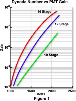
Electrons emitted by the photocathode are accelerated toward the dynode chain, which may contain up to 14 elements. Focusing electrodes are usually present to ensure that photoelectrons emitted near the edges of the photocathode will be likely to land on the first dynode. Upon impacting the first dynode, a photoelectron will invoke the release of additional electron that are accelerated toward the next dynode, and so on. The surface composition and geometry of the dynodes determines their ability to serve as electron multipliers. Because gain varies with the voltage across the dynodes and the total number of dynodes, electron gains of 10 million (Figure 1) are possible if 12-14 dynode stages are employed.
Photomultipliers produce a signal even in the absence of light due to dark current arising from thermal emissions of electrons from the photocathode, leakage current between dynodes, as well as stray high-energy radiation. Electronic noise also contributes to the dark current and is often included in the dark-current value.
| Interactive Tutorial | |||||||||||
|
|||||||||||
Channel photomultipliers represent a new design that incorporates a unique detector having a semitransparent photocathode deposited onto the inner surface of the entrance window. Photoelectrons released by the photocathode enter a narrow and curved semiconductive channel that performs the same functions as a classical dynode chain. Each time an electron impacts the inner wall of the channel, multiple secondary electrons are emitted. These ejected photoelectrons have trajectories angled at the next bend in the channel wall (simulating a dynode chain), which in turn emits a larger quantity of electrons angled at the next bend in the channel. The effect occurs repeatedly, leading to an avalanche effect, with a gain exceeding 100 million. Advantages of this design are lower dark current (picoamp range) and an increase in dynamic range.
Confocal microscopes, spectrophotometers, and many high-end automatic camera exposure bodies utilize photomultipliers to gauge light intensity. Spectral sensitivity of the photomultiplier depends on the chemical composition of the photocathode with the best devices having gallium-arsenide elements, which are sensitive from 300 to 800 nanometers. Photomultiplier photocathodes are not uniformly sensitive and typically the photons are spread over the entire entrance window rather than on one region. Because photomultipliers do not store charge and respond to changes in input light fluxes within a few nanoseconds, they can be used for the detection and recording of extremely fast events. Finally, the signal to noise ratio is very high in scientific grade photomultipliers because the dark current is extremely low (it can be further reduced by cooling) and the gain may be greater than one million.
Contributing Authors
Mortimer Abramowitz - Olympus America, Inc., Two Corporate Center Drive., Melville, New York, 11747.
Michael W. Davidson - National High Magnetic Field Laboratory, 1800 East Paul Dirac Dr., The Florida State University, Tallahassee, Florida, 32310.
BACK TO CONCEPTS IN DIGITAL IMAGING TECHNOLOGY