
Microscope Objectives
Numerical Aperture and Resolution
The numerical aperture of a microscope objective is a measure of its ability to gather light and resolve fine specimen detail at a fixed object distance. Image-forming light waves pass through the specimen and enter the objective in an inverted cone as illustrated in Figure 1. A longitudinal slice of this cone of light shows the angular aperture, a value that is determined by the focal length of the objective.
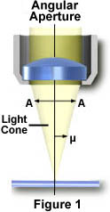
The angle m is one-half the angular aperture (A) and is related to the numerical aperture through the following equation:
where n is the refractive index of the imaging medium between the front lens of the objective and the specimen cover glass, a value that ranges from 1.00 for air to 1.51 for specialized immersion oils. Many authors substitute the variable a for m in the numerical aperture equation. From this equation it is obvious that when the imaging medium is air (with a refractive index, n = 1.0), then the numerical aperture is dependent only upon the angle m whose maximum value is 90�. The sin of the angle m, therefore, has a maximum value of 1.0 (sin(90�) = 1), which is the theoretical maximum numerical aperture of a lens operating with air as the imaging medium (using "dry" microscope objectives).
| Interactive Tutorial | |||||||||||
|
|||||||||||
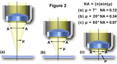
In practice, however, it is difficult to achieve numerical aperture values above 0.95 with dry objectives. Figure 2 illustrates a series of light cones derived from objectives of varying focal length and numerical aperture. As the light cones change, the angle m increases from 7� in Figure 2(a) to 60� in Figure 2(c), with a resulting increase in the numerical aperture from 0.12 to 0.87, nearing the limit when air is the imaging medium.
By examining the numerical aperture equation, it is apparent that refractive index is the limiting factor in achieving numerical apertures greater than 1.0. Therefore, in order to obtain higher working numerical apertures, the refractive index of the medium between the front lens of the objective and the specimen must be increased. Microscope objectives are now available that allow imaging in alternative media such as water (refractive index = 1.33), glycerin (refractive index = 1.47), and immersion oil (refractive index = 1.51). Care should be used with these objectives to prevent unwanted artifacts that will arise when an objective is used with a different immersion medium than it was designed for. We suggest that microscopists never use objectives designed for oil immersion with either glycerin or water, although several newer objectives have recently been introduced that will work with multiple media. You should check with the manufacturer if there are any doubts.
Most objectives in the magnification range between 60x and 100x (and higher) are designed for use with immersion oil. By examining the numerical aperture equation above, we find that the highest theoretical numerical aperture obtainable with immersion oil is 1.51 (when sin (m) = 1). In practice, however, most oil immersion objectives have a maximum numerical aperture of 1.4, with the most common numerical apertures ranging from 1.0 to 1.35.
| Interactive Tutorial | |||||||||||
|
|||||||||||
Visitors are invited to explore changes in numerical aperture with changes in m, using our interactive tutorial that investigates how numerical aperture and magnification are related to the angular aperture of an objective.
The numerical aperture of an objective is also dependent, to a certain degree, upon the amount of correction for optical aberration. Highly corrected objectives tend to have much larger numerical apertures for the respective magnification as illustrated in Table 1 below. If we take a series of typical 10x objectives as an example, we see that for flat-field corrected plan objectives, numerical aperture increases correspond to correction for chromatic and spherical aberration: plan achromat, N.A. = 0.25; plan fluorite, N.A. = 0.30; and plan apochromat, N.A. = 0.45.
Objective Numerical Apertures
|
||||||||||||||||||||||||||||||||||||||||||||||||||||||
Table 1
This feature of increasing numerical aperture across an increasing optical correction factor in a series of objectives of similar magnification holds true throughout the range of magnifications as shown in Table 1. Most manufacturers strive to ensure that their objectives have the highest correction and numerical aperture that is possible for each class of objective.
The resolution of a microscope objective is defined as the smallest distance between two points on a specimen that can still be distinguished as two separate entities. Resolution is a somewhat subjective value in microscopy because at high magnification, an image may appear unsharp but still be resolved to the maximum ability of the objective. Numerical aperture determines the resolving power of an objective, but the total resolution of a microscope system is also dependent upon the numerical aperture of the substage condenser. The higher the numerical aperture of the total system, the better the resolution.
Correct alignment of the microscope optical system is also of paramount importance to ensure maximum resolution. The substage condenser must be matched to the objective with respect to numerical aperture and adjustment of the aperture iris diaphragm for accurate light cone formation. The wavelength spectrum of light used to image a specimen is also a determining factor in resolution. Shorter wavelengths are capable of resolving details to a greater degree than are the longer wavelengths. There are several equations that have been derived to express the relationship between numerical aperture, wavelength, and resolution:
| R = |
(1) |
| R = 0.61 |
(2) |
| R = 1.22 |
(3) |
Where R is resolution (the smallest resolvable distance between two objects), NA equals numerical aperture, ![]() equals wavelength, NA(obj) equals the objective numerical aperture, and NA(Cond) is the condenser numerical aperture. Notice that equation (1) and (2) differ by the multiplication factor, which is 0.5 for equation (1) and 0.61 for equation (2). These equations are based upon a number of factors (including a variety of theoretical calculations made by optical physicists) to account for the behavior of objectives and condensers, and should not be considered an absolute value of any one general physical law. In some instances, such as confocal and fluorescence microscopy, the resolution may actually exceed the limits placed by any one of these three equations. Other factors, such as low specimen contrast and improper illumination may serve to lower resolution and, more often than not, the real-world maximum value of R (about 0.25 mm using a mid-spectrum wavelength of 550 nanometers) and a numerical aperture of 1.35 to 1.40 are not realized in practice. Table 2 provides a list resolution (R) and numerical aperture (NA) by objective magnification and correction.
equals wavelength, NA(obj) equals the objective numerical aperture, and NA(Cond) is the condenser numerical aperture. Notice that equation (1) and (2) differ by the multiplication factor, which is 0.5 for equation (1) and 0.61 for equation (2). These equations are based upon a number of factors (including a variety of theoretical calculations made by optical physicists) to account for the behavior of objectives and condensers, and should not be considered an absolute value of any one general physical law. In some instances, such as confocal and fluorescence microscopy, the resolution may actually exceed the limits placed by any one of these three equations. Other factors, such as low specimen contrast and improper illumination may serve to lower resolution and, more often than not, the real-world maximum value of R (about 0.25 mm using a mid-spectrum wavelength of 550 nanometers) and a numerical aperture of 1.35 to 1.40 are not realized in practice. Table 2 provides a list resolution (R) and numerical aperture (NA) by objective magnification and correction.
Resolution and Numerical Aperture
by Objective Type
|
||||||||||||||||||||||||||||||||||||||||||||||||||||||||||||||||||||||||
Table 2
When the microscope is in perfect alignment and has the objectives appropriately matched with the substage condenser, then we can substitute the numerical aperture of the objective into equations (1) and (2), with the added result that equation (3) reduces to equation (2). An important fact to note is that magnification does not appear as a factor in any of these equations, because only numerical aperture and wavelength of the illuminating light determine specimen resolution. As we have mentioned (and can be seen in the equations) the wavelength of light is an important factor in the resolution of a microscope. Shorter wavelengths yield higher resolution (lower values for R) and visa versa. The greatest resolving power in optical microscopy is realized with near-ultraviolet light, the shortest effective imaging wavelength. Near-ultraviolet light is followed by blue, then green, and finally red light in the ability to resolve specimen detail. Under most circumstances, microscopists use white light generated by a tungsten-halogen bulb to illuminate the specimen. The visible light spectrum is centered at about 550 nanometers, the dominant wavelength for green light (our eyes are most sensitive to green light). It is this wavelength that was used to calculate resolution values in Table 2. The numerical aperture value is also important in these equations and higher numerical apertures will also produce higher resolution, as is evident in Table 2. The effect of the wavelength of light on resolution, at a fixed numerical aperture (0.95), is listed in Table 3.
Resolution versus Wavelength
|
||||||||||||||||||||
Table 3
When light from the various points of a specimen passes through the objective and is reconstituted as an image, the various points of the specimen appear in the image as small patterns (not points) known as Airy patterns. This phenomenon is caused by diffraction or scattering of the light as it passes through the minute parts and spaces in the specimen and the circular back aperture of the objective. The central maximum of the Airy patterns is often referred to as an Airy disk, which is defined as the region enclosed by the first minimum of the Airy pattern and contains 84 percent of the luminous energy. These Airy disks consist of small concentric light and dark circles as illustrated in Figure 3. This figure shows Airy disks and their intensity distributions as a function of separation distance.
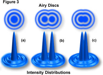
Figure 3(a) illustrates a hypothetical Airy disk that essentially consists of a diffraction pattern containing a central maximum (typically termed a zeroth order maximum) surrounded by concentric 1st, 2nd, 3rd, etc., order maxima of sequentially decreasing brightness that make up the intensity distribution. Two Airy disks and their intensity distributions at the limit of optical resolution are illustrated in Figure 3(b). In this part of the figure, the separation between the two disks exceeds their radii, and they are resolvable. The limit at which two Airy disks can be resolved into separate entities is often called the Rayleigh criterion. Figure 3(c) shows two Airy disks and their intensity distributions in a situation where the center-to-center distance between the zeroth order maxima is less than the width of these maxima, and the two disks are not individually resolvable by the Rayleigh criterion.
| Interactive Java Tutorial | |||||||||||
|
|||||||||||
The smaller the Airy disks projected by an objective in forming the image, the more detail of the specimen that becomes discernible. Objectives of higher correction (fluorites and apochromats) produce smaller Airy disks than do objectives of lower correction. In a similar manner, objectives that have a higher numerical aperture are also capable of producing smaller Airy disks. This is the primary reason that objectives of high numerical aperture and total correction for optical aberration can distinguish finer detail in the specimen.
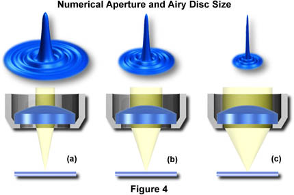
Figure 4 illustrates the effect of numerical aperture on the size of Airy disks imaged with a series of hypothetical objectives of the same focal length, but differing numerical apertures. With small numerical apertures, the Airy disk size is large, as shown in Figure 4(a). As the numerical aperture and light cone angle of an objective increases however, the size of the Airy disk decreases as illustrated in Figure 4(b) and Figure 4(c). The resulting image at the eyepiece diaphragm level is actually a mosaic of Airy disks which we perceive as light and dark. Where two disks are too close together so that their central spots overlap considerably, the two details represented by these overlapping disks are not resolved or separated and thus appear as one, as illustrated above in Figure 3.
| Interactive Tutorial | |||||||||||
|
|||||||||||
An important concept to understand in image formation is the nature of diffracted light rays intercepted by the objective. Only in cases where the higher (1st, 2nd, 3rd, etc.) orders of diffracted rays are captured, can interference work to recreate the image in the intermediate image plane of the objective. When only the zeroth order rays are captured, it is virtually impossible to reconstitute a recognizable image of the specimen. When 1st order light rays are added to the zeroth order rays, the image becomes more coherent, but it is still lacking in sufficient detail. It is only when higher order rays are recombined, that the image will represent the true architecture of the specimen. This is the basis for the necessity of large numerical apertures (and subsequent smaller Airy disks) to achieve high-resolution images with an optical microscope.
In day-to-day routine observations, most microscopists do not attempt to achieve the highest resolution image possible with their equipment. It is only under specialized circumstances, such as high-magnification brightfield, fluorescence, DIC, and confocal microscopy that we strive to reach the limits of the microscope. In most uses of the microscope, it is not necessary to use objectives of high numerical aperture because the specimen is readily resolved with use of lower numerical aperture objectives. This is particularly important because high numerical aperture and high magnification are accompanied by the disadvantages of very shallow depth of field (this refers to good focus in the area just below or just above the area being examined) and short working distance. Thus, in specimens where resolution is less critical and magnifications can be lower, it is better to use lower magnification objectives of modest numerical aperture in order to yield images with more working distance and more depth of field.
Careful positioning of the substage condenser aperture diaphragm is also critical to the control of numerical aperture and indiscriminate use of this diaphragm can lead to image degradation (as discussed in the section on substage condensers). Other factors, such as contrast and the efficiency of illumination, are also key elements that affect image resolution.
Contributing Authors
Mortimer Abramowitz - Olympus America, Inc., Two Corporate Center Drive., Melville, New York, 11747.
Michael W. Davidson - National High Magnetic Field Laboratory, 1800 East Paul Dirac Dr., The Florida State University, Tallahassee, Florida, 32310.
BACK TO ANATOMY OF THE MICROSCOPE