
Köhler Microscope Illumination
A New System of Illumination for Photomicrographic Purposes
Dr. August Köhler
The equipment which can be used with projection apparatus of any kind to illuminate objects with transmitted light originating from a limited artificial light source, can be divided into two groups; the first is constructed so that images of the light source which are formed during the imaging process fall into the object plane and its corresponding planes, while with the other group they appear in planes perpendicular to the (optical) axis at a distance from the object plane, and for the exit pupil of the projection system.
With such kinds of apparatus it is principally necessary to fulfill three conditions, one or another of which, however, may be of lesser importance, depending on the particular purpose. Most important of all, the illuminating apparatus must permit a wide range of variation of numerical aperture and of the direction of incidence of the cone of illuminating rays. Secondly, it is important to illuminate only that part of the object which is imaged, in order if possible to avoid disturbing reflections from the lens mountings, and third, one must, especially for photographic purposes, ensure that the illumination of this part of the object is completely homogenous, since differences of light intensity hardly noticeable to the eye can be very disturbing in a photographic picture.
For photomicrographic purposes, most illumination methods in use at present aim to project an image of the light source into the object plane. These have the disadvantage that when using a light source, which does not provide a homogenous light-emitting area, it becomes rather difficult to obtain completely even illumination of a field of view sufficiently large also for lower magnifications.
In such a case, one tries to reach the required evenness of illumination by using the light source indirectly, that is with a ground-glass screen, or by using appropriate diaphragms which make use of only a very small, completely evenly illuminated part of the effective light source. The first method mentioned naturally leads to loss of light intensity, and therefore, can be used only if the light source is intense enough. With the second method, even using otherwise-adequate light sources (zirconium light and Auer gas light), it is difficult or impossible to achieve uniform illuminations without sacrificing sharp focus of the lamp.
In this case we already have a transition to the system of the second kind, which generally provides more favorable conditions for more homogeneous illumination of an extended visual field. This chiefly funds application when the fulfillment of the requirement is of special importance. This is the case when projecting macroscopic objects with transmitted light (the Scioptikon, enlarging apparatus for photography), and for the projection of microscopic objects with very low-magnification systems (projection system of 70-millimeter and 35-millimeter from Zeiss). Selenka also uses the illumination apparatus of his projection microscope for lower magnifications.
The characteristic location of the image of the light source in or near the exit pupil is already achieved in many cases when the light source is placed at an appropriate distance behind the object plane. This sort of illumination, however, is scarcely usable for this microscope since with the majority of artificial light sources the cone of imaging rays is then too narrow, leading to a loss of light, and also, as a consequence of diffraction phenomena, causing the image to be unclear. One tries to avoid these problems by using simple collecting lenses or specially-designed condenser systems.
The object is then positioned between the condenser and the projection system, and the adjustment of these lenses and the light source with respect to each other, as already indicated above, so chosen that an image of the light source is formed, at least approximately, in the plane which, when used normally, according to the manufacturer's intended application, is the common base of all ray bundles leading to the individual image points, that is into the exit pupil of the projection system.
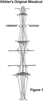
With microscope objectives, which we must particularly consider here, the actual exit pupil may lie in different places along the axis, depending on the position of the iris. In normal use of the microscope with daylight, the exit pupil however is usually replaced by an image of the light-emitting surface (the mirror or the diaphragm of the illuminating apparatus) which, when using medium or high-power objectives, as a rule appears near the back focal plane of the objective. The image of the artificial light source may therefore be moved to near the back focal plane of these objectives. This comes about, as can easily be seen, when the light source is almost in the back focal plane of the condenser. The accompanying diagram (Figure 2) may illustrate the path the light takes, if for the moment one ignores everything below the line A-B, L(1)-L(2) is the light source, located in the lower focal plane of the condenser system (C). The variable O refers to the object plane, three points of which are labeled o(1), o, and o(2). The location of the object is chosen so that it is beyond the focal length of the condenser. P is the objective which serves for projection; for simplicity it is taken that its iris J, which also serves as the exit pupil, is in its back focal plane. In this plane, as can be seen when the light path is followed, an inverted real image of the light source L(1)-L(2) is produced at l(1)-l(2) (for our purposes we can ignore the influence on the image of the light source of diffraction, refraction and absorption by structures in the object). From this image the rays continue further, to the image of the object structure thrown by the projection system; this, however, is omitted from the diagram due to lack of space.
The aperture angle of the cone of rays which meets the object plane at the optical axis is equal to the viewing angle by which the virtual enlarged image of the light source l(1)-l(2) produced in the object plane by the condenser system appears. This can be regulated for the object plane by means of diaphragms which one puts close in front of the light source. For this, however, it is assumed that the opening of the condenser is so large that no part of the virtual image l(1)-l(2) be obscured by it.
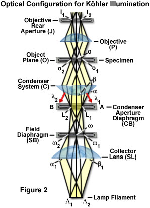
As our illustration shows, the illumination of the whole visual field must be of even intensity, even though the intensity of the individual illuminating points of which the light-source is made up may be different. This is because each small area of the object plane is illuminated by a cone of rays, to which every single point of the source contributes rays, since diverging rays originating from any such point within a given angle (in the figure for example the angle a—L(1)—b) must have equal intensity.
Even though this method has the advantage under the previously mentioned conditions of ensuring homogeneous illumination of the visual field, obstacles stand in the way of its use in other respects. One of these troubles has already been mentioned by R. Zeiss in his instructions on the use of photomicrographic apparatus: the light source is too close to the object, which must be protected from too intense heating by special devices. Further, it is very difficult to regulate the aperture angle of the cone of illuminating rays, and finally it is not possible to achieve a clear delimitation of the illuminated area within the object plane. One has to use diaphragms in the plane of the object stage, but these cannot be brought close enough to the object because of the thickness of the slides, especially when working with higher magnifications.
I have now tried to correct these shortcomings of the procedure without removing the advantage of placing the light source in one of the planes related to the exit pupil.
Overheating of the object can be easily avoided by not placing the light source itself in the back focal plane of the condenser; instead one projects with a suitable collecting lens of not too short focal length, and enlarged or reduced real image of the light source, as required, single points of which act like the corresponding points of the original light source, within an angle determined by the size and distance of the collecting lens. From this image it is easy to occlude parts by placing diaphragms into its plane, and thereby to change the aperture angle of the cone of illuminating rays; this eliminates the second disadvantage mentioned.
The third deficiency is also easily alleviated by positioning the condenser so that the object plane is not within its focal length; a suitable diaphragm, which I shall call the visual field diaphragm, is then placed in a plane related to the object plane by the condenser system. The condenser system then projects a real image of this diaphragm into the object plane; the size and shape of this image depend on the size and shape of the visual field diaphragm.
The simplest case is when the condenser and collecting lenses are positioned so that the visual field diaphragm is place between the two. The path of the light rays can be explained on the diagram we have already mentioned above, but we must now, however, also consider that which lies below the line A-B. The light source is no longer in this plane, but a considerable distance away at L(1)-L(2); L(1)-L(2) represents this image formed by the collecting lens SL. This field diaphragm is designated by SB, o(1), o, and o(2) are the conjugate points of the object points w(1), w, and w(2)-they represent the iris of the collecting lens SL as can be seen from the diagram. During imaging of the light source L(1)-L(2) into L(1)-L(2), this (diaphragm) also serves as the exit pupil, and its size an distance from the lens SL must for all cases be chosen appropriately. That means that all ray bundles reaching the image L(1)-L(2) may be limited only by this (diaphragm) and not by anything elsewhere along the axis, for example a lens mount. Only in this case will the image of the visual field diaphragm in the object plane be completely and uniformly illuminated. (Note: If the ray bundles leading to the image of the light source were bounded by the edge of the lens mount, one would have to produce a sharp image of this edge of the mount in the object plane. If the visible field diaphragm were between the collector lens and the light source, then the exit pupil would be its real or virtual image, and this would have to be projected through the condenser into the object plane.)
I have lately used a bi-convex lens of about 10 centimeters diameter and 25 centimeters focal length, the visual field diaphragm is a simple disc cut from black cardboard, which can be easily mounted and removed from the lens mount. As the condenser on the microscope a simple Abbe illuminating apparatus with a disc diaphragm or iris diaphragm was used. Depending on whether one is using a low magnification system (with large visual field) and narrow diaphragms in the condenser, or high-magnification systems (small visual field) and wide diaphragms, one then positions the collecting lens at a distance from the condenser, which for the first case is smaller, and for the second case larger than twice the focal length. At smaller distances the projected image of the visual field diaphragm produced by the condenser is relatively large, but the image of the light source, will be small; however it nonetheless fills a small diaphragm opening. At longer distances the image of the light source becomes large enough for an open diaphragm and the image of the visual field diaphragm is still large enough for the small visual field, which is projected by higher magnification systems.
First one focuses the object at very low magnification, and positions the collecting lens so that its blurred image appears in the middle of the visual field; one then focuses illuminated from the rear, behind the lens, with which the lens mount contrast sharply. One then removes the screen and positions the light source so that the convex lens projects a clear image of it on to the diaphragm of the illuminating apparatus. If one now looks into the microscope, one sees the image of the convex lens in the middle of the visual field as a sharply defined, completely homogeneously illuminated round disc, on which the object structure appears sharply portrayed. One now exchanges the low power system for the system to be used for photography, and equips the convex lens with a visual field diaphragm, which reduces the lens opening to the size needed for illuminating the visual field.
When using high magnification and a wide-open condenser diaphragm the use of an achromatic condenser system is recommended. The reasons for this are the same as those when using the previously used method of illumination.
Since I have no achromatic condenser at my disposal, I have recently used microscope objectives in place of condensers, and the objective of a small opera glass in place of the convex lens, with great success. Even at higher magnifications one gets a very nice delimitation of the illuminated visual field, since with these accessories the images of the visual field diaphragm are very sharp. Sufficient graduation of the numerical aperture of the cone of illuminating rays can easily be achieved by using objectives of different apertures, possibly reducing their opening with appropriate diaphragms. For this I use the diaphragms for dark field illumination supplied by Zeiss which can be screwed into objectives A to F between the funnel and the lens mount.
When using a carefully constructed optical bench the use of an iris diaphragm as visual field diaphragm is advised, mounted permanently at a fixed distance from the microscope; one must then measure the opening and the focal length of the collecting lens, through which one projects a smaller image of the light source into the focal plane of the condenser, or rather the objective, as required.
This method has also been applied successfully at the local Institute of Zoology for projecting microscope objects during lectures. As the condenser for low magnifications we use a Steinheil loupe with sixfold magnification, and for higher (magnification) an objective 4 from Hartnack.
Concerning the light source I use, my experience covers petroleum light, Argand burners, Auer gas light and zirconium light (burner from Max Wolz in Bonn). Especially when using the two light sources mentioned, my recommended method of illumination has served very well, since in one case the illuminated surface is a glowing net, which must not be projected sharply into the object plane, while in the other case in my experience, small cracks and pits appear very soon in the light-producing body, similarly causing uneven intensity of the luminous surface.
This method should also be well suited to the direct use of the electric arc light, if one projects a sufficiently large image of the positive carbon tip on to the condenser diaphragm. As far as I can gather from diagrams and descriptions available to me, this should be achievable without any great difficulty using the large Zeiss apparatus, and this will be especially advantageous for projection purposes. I could not, however, carry out any experiments of my own since I have neither the Zeiss apparatus nor electric light at my disposal.
Further, experiments with different kinds of magnesium light recommend themselves, especially the light produced by burning a wire or strip of magnesium in a simply constructed lamp.
Cuvettes to absorb heat and light radiation can of course be attached just as with other illumination methods, and these are best placed near the collecting lens.
The light losses are not greater than when one projects an image of the light source into the object plane using an illumination apparatus and a convex lens.
For illuminating with sunlight our method is not applicable unless one uses rather impractical lens combinations, however, one achieves satisfactory results by projecting an image of the sun into the object plane. (Note: To get a large enough image of the sun in the lower (front) focal plane of the condenser one would have to use a simple collecting lens of considerable focal length, or use a compound lens system similar to the Kepler or Dutch telescope, the latter with a ray-path like that of objectives used for telephotography.)
This translation of Dr. Köhler's original paper, which appeared along with one "woodcut" (Figure 1) in Zeitschrift für wissenschaftl. Mikroskopie, 10: pages 433-440 (1893), was first published in "Köhler Illumination Centenary" by the Royal Microscopical Society in 1994.
Contributing Authors
Peter Evennett - Department of Pure and Applied Biology, The University of Leeds, Leeds LS39JT, United Kingdom.
BACK TO ANATOMY OF THE MICROSCOPE