
Microscope Objectives
Immersion Media
The ability of a microscope objective to capture deviated light rays from a specimen is dependent upon both the numerical aperture and the medium through which the light travels.
Numerical aperture is related to the imaging medium through the equation:
Where m is one-half the angular aperture of the objective and n is the refractive index of the medium between the objective front lens and the specimen coverslip.
As is evident from the numerical aperture equation above, an objective's numerical aperture is directly proportional to the refractive index (n) of the imaging medium between the coverslip and the front lens, and also to the sin of one-half the angular aperture of the objective. Because sin m cannot be greater than 90 degrees, the maximum possible numerical aperture is determined by the refractive index of the immersion medium. Most microscope objectives use air as the medium through which light rays must pass between the coverslip protecting the sample and front lens of the objective. Objectives of this type are referred to as dry objectives because they are used without liquid imaging media. Air has a refractive index of 1.0003, very close to that of a vacuum and considerably lower than most liquids, including water (n = 1.33), glycerin (n = 1.470) and common microscope immersion oils (average n = 1.515). In practice, the maximum numerical aperture of a dry objective system is limited to 0.95, and greater values can only be achieved using optics designed for immersion media.
| Interactive Java Tutorial | |||||||||||
|
|||||||||||
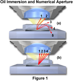
The principle of oil immersion is demonstrated in Figure 1 where individual light rays are traced through the specimen and either pass into the objective or are refracted in other directions. Figure 1(a) illustrates the case of a dry objective with five rays (labeled 1 through 5) shown passing through a sample that is covered with a coverslip. These rays are refracted at the coverslip-air interface and only the two rays closest to the optical axis (rays 1 and 2) of the microscope have the appropriate angle to enter the objective front lens. The third ray is refracted at an angle of about 30 degrees to the coverslip and does not enter the objective. The last two rays (4 and 5) are internally reflected back through the coverslip and, along with the third ray, contribute to internal reflections of light at glass surfaces that tend degrade image resolution. When air is replaced by oil of the same refractive index as glass, shown in Figure 1(b), the light rays now pass straight through the glass-oil interface without deviation due to refraction. The numerical aperture is thus increased by the factor of n, the refractive index of oil. This phenomenon can be explored with the interactive Java tutorial on Immersion Oil and Numerical Aperture.
Microscope objectives designed for use with immersion oil have a number of advantages over those that are used dry. Immersion objectives are typically of higher correction (either fluorite or apochromatic) and can have working numerical apertures up to 1.40 when used with immersion oil having the proper dispersion and viscosity. These objectives allow the substage condenser diaphragm to be opened to a greater degree, thus extending the illumination of the specimen and taking advantage of the increased numerical aperture.
A factor that is commonly overlooked when using oil immersion objectives of increased numerical aperture is limitations placed on the system by the substage condenser. In a situation where an oil objective of NA = 1.40 is being used to image a specimen with a substage condenser of smaller numerical aperture (1.0 for example), the lower numerical aperture of the condenser overrides that of the objective and the total NA of the system is limited to 1.0, the numerical aperture of the condenser.
Modern substage condensers often have a high degree of correction (see our section on condensers) with numerical aperture values ranging between 1.0 and 1.40. In order to effectively utilize all the benefits of oil immersion, the interface between the substage condenser front lens and the underside of the microscope slide containing the specimen should be also be immersed in oil. An ideal system is schematically diagramed in Figure 2, where immersion oil has been placed at the interfaces between the objective front lens and the specimen slide and also between the front lens of the condenser and the underside of the specimen slide.
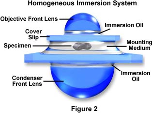
This system has been termed a Homogeneous Immersion System and it is the ideal situation to achieve maximum numerical aperture and resolution in an optical microscope. In this case, the refractive index and dispersion of the objective front lens, immersion oil, substage condenser front lens, and the mounting medium are equal or very near equal. In this ideal system, an oblique light ray can pass through the condenser lens and completely through the microscope slide, immersion oil, and mounting medium undeviated by refraction at oil-glass or mounting medium-glass interfaces.
When using high-power achromat oil immersion objectives, it is sometimes permissible to omit the step of oiling the condenser top lens. This is because the condenser aperture diaphragm must often be reduced with lesser-corrected objectives to eliminate artifacts and provide optimum imaging. The reduction in diaphragm size reduces the potential increase in numerical aperture (provided by oiling the condenser lens) so the loss in image quality under these conditions is usually negligible.
There are a variety of commercially available synthetic oils that have been designed to optimize immersion microscopy techniques. Many countries have published their own standards for the necessary qualities of immersion oils and the International Standards Organization has recognized the ISO 8036 standard optical properties for general purpose immersion oils:
ne = 1.5180 � 0.0005 (nD = 1.515)
Ve = 44 � 3 (Abbe Number - a measure of dispersion)
Temperature = 23 � 0.1 degrees Centigrade
In addition to stringent control of the optical properties, immersion oils must also exhibit suitable physicochemical features such as being non-drying, inert to optical surface coatings, non-fluorescing, chemically inert, non-toxic, and easy to remove. Most microscope manufactures supply a specialized immersion oil with their objectives that is specifically matched to the dispersion properties of the objective. Make sure that any aftermarket oils you purchase meet dispersion criteria matching the objective for which the oil is intended. A number of older commercially-produced immersion oils (particularly those manufactured more than 10 years ago) contained significant amounts of polychlorinated biphenyls. These oils are carcinogenic and should be avoided, however most newer immersion oils are made without this dangerous chemical and are perfectly safe to use. The premier manufacturer of immersion media is Cargille Laboratories, Inc., of Cedar Grove, New Jersey who manufactures five standard types of oils:
Normal Light Microscopy - The most common immersion oil meeting two viscosity requirements (Types A and B): 150 and 1250 centistokes. These oils can be blended to produce intermediate viscosities.
High Viscosity Oil (Type NVH) - Having a viscosity of 21,000 centistokes, this oil is popular for inverted, horizontal, and inclined applications and also for very long working distance objectives and samples that utilize wide condenser gaps.
Fluorescence Microscopy (Type DF) - An oil that yields the highest resolution with fluorescence microscopy. This oil produces a background color that is pale green.
Fluorescence Microscopy (Type FF) - Improved oil that has essentially no background fluorescence and is crystal clear and non-hydroscopic. This oil is often termed "universal" oil because it can be substituted with confidence for virtually any other immersion oil for fluorescence applications.
Table 1 lists the properties of the three most common types of Cargille Laboratories immersion oils.
Cargille Immersion Oils
|
||||||||||||||||||||||||||||||||||||||||||
Table 1
A primary problem with common immersion oils is their inherently high absorption characteristics in the ultraviolet region of the spectrum (below about 375 nanometers). This does not affect a majority of the visible light optical microscopy done with immersion media, but it can lead to trouble when attempting to image specimens at wavelengths below 400 nanometers. The ultraviolet absorption of glycerin is negligible in the 400-350 nanometer region, so the pure solvent, or a 90:10 mixture with water, could be used for immersion techniques with near ultraviolet microscopy.
Infrared (IR) microscopy is also complicated with artifacts arising from the absorption of immersion materials at wavelengths exceeding 700 nanometers. The only practical media for IR microscopy is paraffin oil, which is also useful for fluorescence immersion microscopy because it has negligible fluorescence at wavelengths down to 350 nanometers.
The immersion media listed in Table 2 have a wide spectrum of refractive indices and are useful for a variety of different optical microscopy techniques. Most of the media with refractive indices equal to or lower than that of glass are used in common biological brightfield, phase contrast, DIC, and fluorescence microscopy. Those media with very high refractive indices, such as bromonaphthalene and methylene iodide, are used with specialized objectives to achieve the highest numerical aperture and resolution possible and are also very useful in reflected light microscopy for materials that have very low or varying reflectance.
Common Immersion Media
|
||||||||||||||||||||||
Table 1
Modern advances in tissue and cell culture techniques have sparked an interest in being able to image living cells and tissues that are bathed in physiological saline solution. Cellular dynamics inside living tissues are currently being heavily studied with quantitative optical imaging techniques including confocal, differential interference contrast (DIC), and epi-fluorescence microscopy. The average refractive index of living cells is 1.35, very close to that of the surrounding buffered aqueous-saline solution (n = 1.33) that must be present to support ongoing cellular activities. A problem arises when using long working distance dry objectives to visualize cells in aqueous tissue culture due to reflections from the surface of the liquid that will obscure details of the specimen. Likewise, the use of oil immersion objectives to observe living cells is also problematic due to refractive index differences between the aqueous imaging medium and the glass of the objective's front lens.
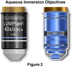
The objectives illustrated in Figure 3 are designed to be used for imaging cells and tissues in buffered saline solution, while providing plenty of room for micromanipulation of the sample during observation. The nose (or dipping cone), housing the front lens elements of the objective is tapered at a 43-degree angle to allow a steep inclination of approach providing easy access to the sample by the manipulator or microelectrodes while keeping the specimen and objective immersed in solution. These objectives also have long working distances ranging from 2.0 mm (60x Plan Fluorite) to 3.3 mm (10x - 40x Plan Fluorite) that are also useful in allowing additional room for micromanipulation of the sample. Numerical apertures in this series of objectives are comparable (and often slightly higher) to those found in typical dry Plan Fluorites. Objectives of this type are manufactured by all of the major microscope companies including Olympus, Zeiss, Leica, and Nikon, and often the manufacturers provide additional accessories useful in micromanipulation of tissue culture samples and other biological samples.
An excellent demonstration of resolution and enhancement of fine detail seen by water immersion objectives is illustrated in Figure 4 with the observation of living rat cremaster muscle in tissue culture.
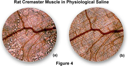
Figure 4(a) is a photomicrograph of the rat tissue taken with a normal dry 4x objective positioned just above the air/water interface. Note the distortion and blurring of the sample that occurs due to reflections from the surface of the water. These effects are eliminated in Figure 4(b), which is a photomicrograph of the same viewfield, but using a 4x water immersion objective. This image is considerably sharper and displays a greater resolution of fine detail than that provided by the dry objective.
Another problem with imaging tissue samples is the limited range of resolution and illumination intensity exhibited by oil immersion objectives when examining specimens at high magnification. Immersion objectives typically lose their excellent imaging properties at depths exceeding 10 microns into the sample when it is covered by a coverslip and bathed in aqueous solution. This problem is illustrated in Figure 5(a) where ray tracing indicates that a sphere in aqueous media is distorted into an apparently elongated oval when using an oil immersion objective to image the sample through immersion oil having n = 1.515.
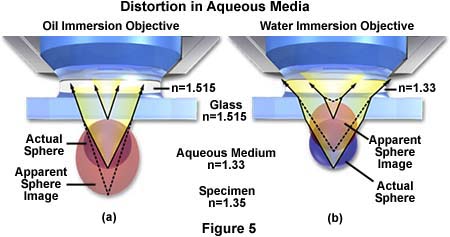
The same sphere remains spherical when using a water immersion objective, even though the imaging rays must still pass through the glass coverslip with a refractive index equal to 1.515. Water immersion objectives also eliminate spherical aberrations that are often produced when viewing specimens through an aqueous solution. These advanced objectives also have an increased axial resolution that often equals the theoretical limits for the numerical aperture and they produce exceptional contrast, resolution, and provide a higher intensity of illumination.
Technical Tips for Oil Immersion Microscopy
The first rule in microscopy is to keep the optical elements completely free of dust, dirt, oil, solvents, and any other contaminants. The microscope should be kept in a low vibration smoke-free room that is clean as possible and has minimal disturbance of the circulated air. Use a dust cover on the microscope when not in use and keep all accessories in air-tight containers. Avoid using corrosive solvents to clean any part of the microscope, and use only diluted soapy water to clean non-optical surfaces. Oil should be used keeping the following techniques and precautions in mind:
The first step is to locate the sample with a low-power objective and position the microscope slide so that the area of interest is squarely in the central portion of the stage opening. It is often desirable to rotate the immersion objective (without oil) into place to ensure the correct location of the specimen. To achieve optimum results when using the oil immersion technique it is important to also apply oil to the underside of the microscope slide and to the top lens of the substage condenser to form an oil bead between the two, as described below. Most modern microscopes provide a relatively wide oval-shaped opening in the mechanical stage to allow oil to be used in the area between the bottom of the microscope slide and the front lens of the condenser.
Swing the immersion objective to a position in the nosepiece where it will be the next objective rotated into the optical pathway directly above the specimen. Use a piece of lint-free paper or an eyedropper to place a small droplet of oil directly on the front lens of the immersion objective. Next, place another droplet of oil on the cover glass immediately above the area to be imaged. Many of the newer oil immersion objectives manufactured by Olympus and Nikon use plano-concave front lenses in their immersion objectives, and it is imperative that the step of oiling the objective front lens not be omitted with these objectives. Failure to fill the concave "cavity" in these objectives may result in entrapment of a tiny air bubble resulting in severe flare and image degradation.
Slowly lower the oil objective into the small pool of oil on the microscope coverslip using the coarse focusing adjustment knob. When the oil-covered objective front lens makes contact with the oil on the coverslip, a small flash of scattered light will be emitted at the oil junction, indicating that the two oil pools have merged. Be very careful with this step, because racking the objective too close to the coverslip can cause a collision between the two, possibly resulting in damage.
Bring the specimen slowly into focus using the coarse adjustment until details just begin to become visible, and then switch to the fine adjustment to bring the specimen into proper focus. It is important to remember that the working distance of most fluorite and apochromat objectives is less than one-tenth of a millimeter, resulting in a very narrow range of adjustment of the fine focus knob, so carefully monitor the objective's approach to the oil pool while lowering it with either the coarse or fine adjustment. Although most high-power immersion oil objectives have spring-loaded front ends that can be retracted into the body of the objective, careless use of these objectives can still drive the objective into the specimen slide causing damage.
An alternative method used by many microscopists is to position the area to be imaged in the center of the microscope's optical path using lower power objectives. Next, the oil immersion objective (without oil) is placed into the optical path and the specimen area of interest is roughly brought into center of the viewfield and focused. This pre-positions all of the components of the system in preparation for the addition of oil. Swing the immersion objective to an adjacent stop on the microscope nosepiece and apply oil both to the objective front lens and specimen as discussed above. Next, quickly rotate the oiled objective into position above the specimen merging the two oil droplets (one on the sample and one on the objective) into a single pool. The specimen is now ready for observation and photomicrography.
For applying oil to the front lens of the substage condenser, use the following considerations:
Make certain that the mechanical stage of the microscope has an opening of sufficient size to allow scanning of the oiled specimen without spilling oil onto the bottom of the stage. Many advanced research microscopes have a stage insert that is removable for use with oil. Remove the specimen slide from the microscope stage before applying oil to the condenser top lens.
In a manner similar to oiling an objective, place a drop of oil on the bottom of the microscope slide and apply a similar drop to the front lens of the substage condenser. Make sure that the condenser is slightly lowered in its rack before replacing the microscope slide on the stage. After the slide has been placed on the stage, rack the condenser back to the proper position while carefully observing the oil droplets on the condenser lens and microscope slide. These droplets should merge into one as the condenser is brought into proper position.
As you scan the surface of an oiled microscope slide, periodically observe the position of the stage with respect to the objective and condenser front lens to assure that there is a continuous bead of oil between these elements and the microscope slide. When scanning over a large area on a microscope slide, it is often necessary to reapply some oil to assure continuity of the imaging medium.
|
||||||||
Contributing Authors
Mortimer Abramowitz - Olympus America, Inc., Two Corporate Center Drive., Melville, New York, 11747.
Michael W. Davidson - National High Magnetic Field Laboratory, 1800 East Paul Dirac Dr., The Florida State University, Tallahassee, Florida, 32310.
BACK TO ANATOMY OF THE MICROSCOPE