Microscope Optical Components
Introduction
Modern compound microscopes are designed to provide a magnified two-dimensional image that can be focused axially in successive focal planes, thus enabling a thorough examination of specimen fine structural detail in both two and three dimensions.
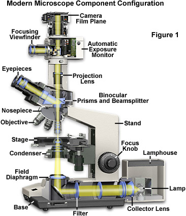
Most microscopes provide a translation mechanism attached to the stage that allows the microscopist to accurately position, orient, and focus the specimen to optimize visualization and recording of images. The intensity of illumination and orientation of light pathways throughout the microscope can be controlled with strategically placed diaphragms, mirrors, prisms, beamsplitters, and other optical elements to achieve the desired degree of brightness and contrast in the specimen.
Presented in Figure 1 is a typical microscope equipped with a trinocular head and 35-millimeter camera system for recording photomicrographs. Illumination is provided by a tungsten-halogen lamp positioned in the lamphouse, which emits light that first passes through a collector lens and then into an optical pathway in the microscope base. Also stationed in the microscope base is a series of filters that condition the light emitted by the incandescent lamp before it is reflected by a mirror and passed through the field diaphragm and into the substage condenser. The condenser forms a cone of illumination that bathes the specimen, located on the microscope stage, and subsequently enters the objective. Light leaving the objective is diverted by a beamsplitter/prism combination either into the eyepieces to form a virtual image, or straight through to the projection lens mounted in the trinocular extension tube, where it can then form a latent image on film housed in the camera system.
The optical components contained within modern microscopes are mounted on a stable, ergonomically designed base that allows rapid exchange, precision centering, and careful alignment between those assemblies that are optically interdependent. Together, the optical and mechanical components of the microscope, including the mounted specimen on a glass micro slide and coverslip, form an optical train with a central axis that traverses the microscope base and stand. The microscope optical train typically consists of an illuminator (including the light source and collector lens), a substage condenser, specimen, objective, eyepiece, and detector, which is either some form of camera or the observer's eye (Table 1). Research-level microscopes also contain one of several light-conditioning devices that are often positioned between the illuminator and condenser, and a complementary detector or filtering device that is inserted between the objective and the eyepiece or camera. The conditioning device(s) and detector work together to modify image contrast as a function of spatial frequency, phase, polarization, absorption, fluorescence, off-axis illumination, and/or other properties of the specimen and illumination technique. Even without the addition of specific devices to condition illumination and filter image-forming waves, some degree of natural filtering occurs with even the most basic microscope configuration.
Microscope Optical Train Components
|
|
||||||||||||||||||||||||||||
|
|
|
||||||||||||||||||||||||||||
Table 1
While some of the microscope optical components act as image-forming elements, others serve to produce various modifications to illumination of the specimen and also have filtering or transforming functions. Components involved in formation of images by the microscope optical train are the collector lens (positioned within or near the illuminator), condenser, objective, eyepiece (or ocular), and the refractive elements of the human eye or the camera lens. Although some of these components are not typically thought of as imaging components, their imaging properties are paramount in determining the final quality of the microscope image.
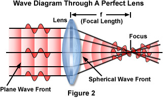
Fundamental to the understanding of image formation in the microscope is the action of individual lens elements that comprise the components in the optical train. The simplest imaging element is a perfect lens (Figure 2), which is an ideally corrected glass element that is free of aberration and focuses light onto a single point. A parallel, paraxial beam of light passes through the converging lens and is focused, by refraction, into a point source located at the focal point of the lens (the point labeled Focus in Figure 2). Such lenses are often referred to as positive lenses because they induce a convergent light beam to converge more rapidly, or cause a divergent light beam to diverge less rapidly. A point source of light located at the lens focal point emerges as a paraxial, parallel beam of light as it leaves the lens, moving from right to left in Figure 2. The distance between the lens and the focal point is referred to as the focal length of the lens (denoted by the distance f in Figure 2).
Optical phenomena are often explained either in terms of quantum theory or wave mechanics, depending upon the particular problem that is being described. In considering the action of lenses, the wave-like properties can often be ignored and light is considered to travel in straight lines often termed rays. Simple ray diagrams are sufficient to explain many important aspects of microscopy including refraction, focal length, magnification, image formation, and diaphragms. In other instances, it is convenient to refer to light waves as being composed of discrete particles (quanta), especially when light is generated by quantum mechanical events or transformed into other forms of energy. This discussion will be restricted to optical lens models utilizing paraxial rays that conform to both the wave-like nature of light and to simple ray diagrams in which light travels from left to right. Paraxial light rays are those traveling very close to the optical axis, resulting in incident and refraction angles that are very small, which when measured in radians, can be considered as equal to their sine values.
In a parallel beam of light, individual monochromatic light waves form a wavetrain having a combination of electric and magnetic vectors vibrating in phase to form a wavefront, which has a vibration orientation perpendicular to the direction of wave propagation. The plane wave is converted to a spherical wave as it passes through the perfect lens, with the front centered at the focal point (Focus) of the lens (Figure 2). Light waves arrive at the focal point in phase and interfere constructively with each other at this location. Alternatively, light comprising a spherical wavefront emanating from the focal point of a perfect lens is converted by the lens into a plane wave (proceeding from right to left in Figure 2). Each light ray in the plane wave undergoes a different change of direction upon encountering the lens because it arrives at the surface in a slightly different angle of incidence. Upon emerging from the lens, the direction of the light ray also changes. In real systems, the angle of refraction and focal point of a lens or group of lenses is dependent upon the thickness, geometry, refractive index, and dispersion of each component in the system.
| Interactive Tutorial |
|
||||||||||
|
|||||||||||
The general action of a perfect lens (or lens system) is to convert one spherical wave into another, with the geometrical properties of the lens determining the position of the focal point. As the distance of the light source from the lens is increased, the angle of diverging light rays entering the lens is decreased with a corresponding increase in the radius of the wavefront. If the radius of a spherical wave entering the lens is infinite, the radius of the spherical wave passing through the lens becomes equal to the focal length of the lens. A perfect lens has two focal points, and a plane wave passing through the lens is focused onto one of these points, depending upon whether the light rays enter from the left or right side of the lens.
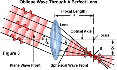
In situations where the propagation direction of the plane wave does not coincide with the optical axis of the lens, the focal point of the spherical wave produced by the lens is also removed from the axis. Figure 3 illustrates the case of a plane wavefront encountering a perfect lens when tilted at an angle (a). The center of the resulting spherical wave is labeled S and lies at a distance d from the axial focal point (labeled Focus in Figure 3), but within the same focal plane. The value of d can be expressed as:
where f is the focal length of the perfect lens. In terms of geometric optics, f is a value that refers to the radius of an arc centered on S and passing through the center of the lens as if it were a single refracting surface.
An alternative model for investigating a point source of light (S(1)) that does not lie in the focal plane of a lens is illustrated in Figure 4. In this figure, the perfect lens is dissected into two individual lens elements (Lens(a) and Lens(b)), such that the point source of light S(1) is positioned a distance equal to f(a) (the focal length) away from Lens(a). Likewise, the point source S(2) is positioned at a distance of f(b), the focal length of Lens(b). A straight line connecting the centers of Lens(a) and Lens(b) is referred to as the optical axis of the lens system.
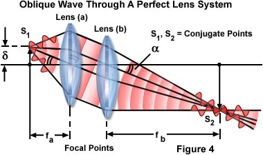
In the dual-lens system (Figure 4), a spherical wavefront emanating from light source point S(1), and located at a distance d from the optical axis of the lens, is converted by Lens(a) into a plane wave. As it exits from Lens(a), the plane wave is tilted with respect to the lens axis by an angle a. Both d and a are related by the sine equation discussed above, with the value for f being replaced by f(a). After passing through the second lens (Lens(b)), the plane wave is converted back into a spherical wave having a center located at S(2). The result is that the perfect lens L, which equals Lens(a) + Lens(b), focuses light from point S(1) onto point S(2) and also performs the reverse action by focusing light from point S(2) onto point S(1). Focal points having such a relationship in a lens system are commonly referred to as conjugate points.
In the nomenclature of classical optics, the space between light source S(1) and the entrance surface of the first lens is referred to as the object space, while the region between the second lens exit surface and point S(2) is known as the image space. All points involved with primary or secondary light rays are termed objects (or specimens in optical microscopy), while the regions containing light rays concentrated by refraction from the lens are called images. If the light waves intersect, the image is real, whereas if only the projected extensions of refracted light rays intersect, a virtual image is formed by the lens system. A real image can be visualized when projected onto a screen, captured on photographic film emulsion, or organized into a digital array by the photodiode elements of a charge-coupled device (CCD). Conversely, a virtual image requires the assistance of another lens or lens system to be seen by an observer.
| Interactive Tutorial |
|
||||||||||
|
|||||||||||
If the point S(1) in Figure 4 is expanded into a series of points spread throughout the same focal plane, then a perfect lens will focus each point in the series onto a conjugate point in the focal plane of S(2). In the case where a point set of S(1) lies in a plane perpendicular to the optical axis of the lens, then the corresponding conjugate points in set S(2) would also lie in a plane that is perpendicular to the axis. The reverse is also true: the lens will focus every point in the set S(2) onto a conjugate point on the plane or surface of point set S(1). Corresponding planes or surfaces of this type are known as conjugate planes.
An alternative method of representing a train of propagating light waves is illustrated in Figure 5 for an oblique light wave. This method relies on applying the laws of geometrical optics to determine the size and location of images formed by a lens or multi-lens system. Two representative light rays, one paraxial and one traveling through the center of the lens (the principal ray), are all that is necessary to establish the parameters of the imaging situation. Many textbooks on Gaussian optics refer to these light rays as characteristic rays, with the principal ray being the one that passes through the center of the entrance and exit pupils, the lens, and any aperture diaphragms present in the optical system. Often, the principal ray is omitted from consideration and the characteristic rays passing through the front and rear focal points of the lens are utilized to define the object and image size and location. In Figure 5, the second characteristic ray is illustrated as a yellow-filled dotted line passing through the front focal point (F') of the lens.
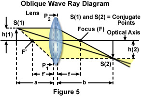
The specimen or light source is designated S(1) in Figure 5, and is located at distance a to the left of the lens, in the region known as the object space. A single light ray, designated by the dotted line emanating from S(1) and intersecting the optical axis at the object-side focal point (F'), is refracted by both surfaces of the lens and exits parallel to the optical axis. Extensions of the refracted and incident ray intersect at a surface within the lens located at distance a from the source (S(1)). This surface is known as the first or object-side principal surface, and is designated by P(1) in Figure 5. The uppermost light ray, progressing from S(1) in a direction parallel to the optical axis, is refracted by the lens and passes through the image-side focal point (F). Extensions of the refracted and incident ray intersect at the image-side principal surface (noted as P(2) in Figure 5) within the lens and positioned at distance b from the image point S(2). Near the vicinity of the lens axis, the surfaces P(1) and P(2) approximate plane surfaces and are known as the principal planes of the lens. The intersections of these planes with the optical axis of the lens (not illustrated) are referred to as the principal points. Simple convex lenses exhibiting bilateral symmetry have principal points that are symmetrical with the lens surfaces. More complex lenses and multiple lens systems often have principal points that coincide with the surface of the lens or even extend outside the glass elements.
Another set of points utilized to define lens parameters are the nodal points, which occur where the extensions of oblique light rays passing through the lens intersect the optical axis. Nodal points are not illustrated in Figure 5, but would lie very close to the principal points of the lens. Thus, three pairs of points, the lens focal points (F and F'), principal planes (P(1) and P(2)), and the principal nodes all lie on the lens optical axis. If the location of the focal points and either the principal points or the nodal points is known, then geometrical construction of ray traces to elucidate object and image parameters can be undertaken without considering refraction of light rays at each surface of the lens. The result is that any lens system can be simulated utilizing only the focal points and principal planes by drawing ray traces as if they encounter the first principal plane, travel parallel to the optical axis, and emerge from the second principal plane without refraction.
| Interactive Tutorial |
|
||||||||||
|
|||||||||||
Note that distance a is greater than the lens front focal length, f' in Figure 5. Under these circumstances, an inverted image (S(2)) is then formed in the image space at a distance b to the right of the lens. The length of b is greater than the lens rear focal length, f, which is related to the distances a and b by the classical lens equation:
The height of image S(2) is denoted by the quantity h(2), and represents an increase in size, resulting from magnification of the object or specimen S(1) positioned at the front of the lens and having a height of h(1). The lateral magnification, M of this simple lens (which approximates a Gaussian thin lens) is expressed by the equation:
Because S(1) and S(2) lie in conjugate planes, the image S(2) will be focused at S(1) by the lens. The focal length would then be represented by f' and the magnification (M) inverted to 1/M due to the reduction in size of the image when the reverse situation is considered.
The distance ratio between two image points along the optical axis on the object side of the lens and two conjugate points on the image side is known as the longitudinal or axial magnification. The magnitude of the longitudinal magnification is the square of the lateral magnification for small distances from the image plane.
All of the imaging components in the optical microscope are governed by the basic geometrical relationships described above. This includes the collector lens, condenser, objective, eyepieces (in the projection mode), camera system, and the human eye.
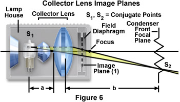
The first stage of the microscope optical train is the lamphouse, which contains the lamp and collector lens, and is responsible for establishing the primary illumination conditions for the microscope. Illustrated in Figure 6 is a schematic diagram of a typical lamp and collector lens configuration. Image sizes and positions are presented according to the conventions introduced in Figure 5 for a basic primary lens system. Light emitted by the tungsten-halogen lamp is passed through the collector lens system and the filament is focused onto the front focal plane of the condenser. The first image plane in the microscope optical train (Image Plane (1)) occurs at the position of the field diaphragm.
| Interactive Tutorial |
|
||||||||||
|
|||||||||||
Point S(1) on the lamp filament is conjugate to point S(2), which is imaged in the focal plane of the condenser aperture diaphragm when the microscope is configured to operate under conditions of Köhler illumination. The distance from S(1) to the first principal plane of the collector lens system is denoted by distance a, and the distance from the condenser iris diaphragm to the image-side principal plane of the collector is given by distance b. The microscope field diaphragm (Figures 6 and 7) governs the diameter of the light beam emitted by the illumination system before it enters the condenser aperture.
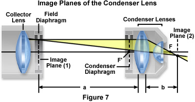
The relationship between conjugate image planes in the condenser lens and the illumination system are illustrated in Figure 7. The field diaphragm (Image Plane (1)) is imaged in the same plane as the specimen (Image Plane (2)) when the microscope is configured for Köhler illumination. The front focal plane of the condenser (F') resides in the center of the aperture diaphragm. Lengths a and b represent the respective distances of the field diaphragm (Image Plane (1)) and the specimen plane (Image Plane (2)) from the principal planes of the condenser lens elements. Light emitted by the lamphouse and passing through the condenser is formed into a cone of illumination that bathes and subsequently passes through the specimen. Adjustment of the condenser aperture iris diaphragm opening size controls the numerical aperture of this illumination cone.
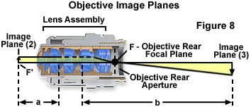
Image planes of the objective are presented in Figure 8, which illustrates a typical objective internal lens system, the specimen plane (Image Plane (2)), and the relative position of the microscope intermediate image (Image Plane (3)). The specimen plane is conjugate to the intermediate image plane, and each are separated from the objective principal planes by distances a and b, respectively. The objective front focal point is designated F', while the rear focal point, which occurs in the plane of the objective rear aperture, is noted as F. Internal lens elements are often complex assemblies consisting of hemispherical and meniscus lenses, lens doublets and triplets, and single lens elements of varying design.
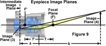
The eyepiece (or ocular) is designed to project either a real or virtual image, depending upon the complex relationship between the intermediate image plane, the eyepiece focal planes, and the internal eyepiece field diaphragm. In addition, the diameter of the fixed eyepiece diaphragm also determines the linear field size observed by the microscopist. This value is termed the field number or field of view number (abbreviated FN) and is often inscribed on the eyepiece housing exterior.
Image planes of the eyepiece, when utilized in projection mode, are presented in Figure 9. The principal focal points are F' and F, the front and rear focal points, respectively. The intermediate image plane (Image Plane (3)) is located in the center of the fixed eyepiece field diaphragm, which is placed either before or after the eyepiece field lens, depending upon the design. This image plane is conjugate to Image Plane (4) and is the location into which eyepiece focusing and measuring reticles are inserted. The length a represents the distance from the eyepiece fixed diaphragm to the principal plane of the eye lens (the lens closest to the observer's eye), while b is the distance from the eye lens to Image Plane (4), located on the sensor surface. Because a is greater than the front focal length of the eye lens (f'), the image formed at Image Plane (4) is a real (not virtual) image. The quantity f denotes the distance from the eye lens to the eyepiece rear focal plane (F), and also represents rear focal length of the eyepiece lens system.
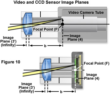
Image planes on a video and CCD sensor are presented in Figure 10, which illustrates the application of a specialized positive projection lens for imaging onto these sensors. The focal point (F) is located either on the video tube photocathode or the CCD photodiode array surface, depending upon the geometry and other parameters of the detector. If the projection lens is located after the eyepiece in the optical train, then it converges the virtual image (located at Image Plane (3')) onto the sensor surface at Image Plane (4). This image plane is located at distance b from the projection eye lens, which is equal to the focal length of the lens. It should be noted that a conventional film camera system can also be employed in place of a video or CCD sensor, in which case the image plane coincides with the plane of the chemical emulsion layered onto the film base.
| Interactive Tutorial |
|
||||||||||
|
|||||||||||
When images are examined in the microscope, an intermediate image (see Image Plane (3) in Figure 11) is formed by the objective at a distance a, which is slightly closer to the eyepiece than its front focal length (F'). This prevents the formation of a real image after the ocular lens, as was illustrated in Figure 9 for the eyepiece operating in projection mode. Together, the eye and eyepiece form an image on the retina (Image Plane (4)) as though the eye were seeing the virtual image.
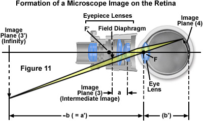
In situations where distance a is less than the focal length, then the reciprocal equation relating focal length to a and b reveals that b must be less than zero. Therefore, a real image is not formed to the right of the eyepiece in the absence of the eye or a camera. Instead, a virtual image (Image Plane (3')) appears at a distance corresponding to -b (Figure 11) to the left of the eyepiece (or b to the right; see Figure 5). When observing the image through the eyepiece, the image-forming beam diverging out through the eye lens appears to originate from the virtual source (located at Image Plane (3')). Light rays exiting the eyepiece form a cone of illumination that constitutes the exit pupil of the microscope, which is also commonly referred to as the eye point or Ramsden disc. For proper observation of magnified specimens, the microscope exit pupil must coincide with the pupil of the observer's eye.
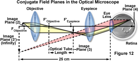
Image planes 2, 3, 3', and 4 (Figures 7-11) are related to each other geometrically as illustrated in Figure 12. In all of the imaging steps, with the exception of Image Plane (3'), the image is real and inverted (see Figures 7-11). When the microscope eyepiece is used for direct viewing (Figure 11) rather than for projection (Figure 9), the image at Image Plane (3') is not real, but virtual and is not inverted relative to the intermediate image. The human eye will not perceive the image on the retina (Image Plane (4)) as inverted, even though the image is inverted in relation to the intermediate image (Image Plane (3)) and the virtual image (located at Image Plane (3')).
Several of the principal image planes in the microscope occur either in fixed or adjustable apertures or diaphragms, which are essential components of all optical systems. A diaphragm, also referred to as a stop, is an opaque gate or a lens mount with a circular opening (often adjustable) that controls light flow through the microscope. Two basic types of diaphragms are utilized in the microscope: the aperture diaphragm, which adjusts the aperture angles in the microscope, and the field diaphragm that controls the size of the field imaged by the instrument. The primary role of diaphragms in the optical microscope is to prevent light rays with severe aberration and stray light from reaching the image planes, and to ensure a suitable distribution and intensity of light in both the object and image space.
Classical microscope design relies on two apertures and two diaphragms to control passage of light through the microscope. The field diaphragm, positioned in the lamphouse or in the base of the microscope, is an adjustable iris-type diaphragm that determines the size of the illuminating field of light. Positioned at the condenser front focal plane is the condenser aperture, another iris diaphragm that is utilized to adjust the beam size and angle of light rays striking the specimen. The third aperture has a fixed size and is located at the rear focal plane of the objective. This aperture determines the diameter of objective exit pupil and size of the intermediate image, while a conjugate fixed diaphragm in the eyepiece (the eyepiece field diaphragm) determines the size of the viewfield seen by the microscopist.
The total magnification of the microscope can be determined by considering properties of the objective and eyepieces. Objectives are corrected for a particular projection distance, which is specific to the magnification and is approximately equal to the optical tube length. In a fixed tube length microscope, this projection distance is about 160 millimeters. Therefore, an 8-millimeter focal length objective would have a lateral magnification of about 20x (160/8) with a corresponding longitudinal magnification of 400x (20×20).
For visual observation, the eyepiece magnification is assumed to be unity when a specimen (or image) is placed at a distance of 250 millimeters from the eye of the observer. In this regard, an eyepiece having a focal length of 25 millimeters would have a magnification value of 10x (250/25). The total microscope magnification for visual observation is computed by taking the product of the objective and eyepiece magnifications. For the objective and eyepiece just described, the total lateral magnification would be about 200x (10x eyepiece multiplied by the 20x objective). It should be noted that a majority of modern research microscopes are equipped with infinity-corrected objectives that no longer project the intermediate image directly into the intermediate image plane. Light emerging from these objectives is instead focused to infinity, and a second lens, known as a tube lens, forms the image at its focal plane. Wavetrains of light leaving the infinity-focused objective are collimated, allowing introduction of auxiliary components, such as differential interference contrast (DIC) prisms, polarizers, and epi-fluorescence illuminators, into the parallel optical path between the objective and the tube lens with only a minimal effect on focus and aberration corrections.
| Interactive Tutorial |
|
||||||||||
|
|||||||||||
Magnification of the intermediate image with infinity-corrected optical microscope systems is determined by the ratio of the focal lengths of the tube lens and objective lens. Because the focal length of the tube lens varies between 160 and 250 millimeters (depending upon the manufacturer and model), the focal length of the objective can no longer be assumed to be 160 millimeters divided by its magnification. Thus, an objective having a focal length of 8 millimeters in an infinity-correct microscope with a tube lens focal length of 200 millimeters would have a lateral magnification of 25x (200/8).
Older finite, or fixed tube length, microscopes have a specified distance from the nosepiece opening, where the objective barrel is secured, to the ocular seat in the eyepiece tubes. This distance is referred to as the mechanical tube length of the microscope. The design assumes that when the specimen is placed in focus, it is a few microns further away than the front focal plane of the objective. Finite tube lengths were standardized at 160 millimeters during the nineteenth century by the Royal Microscopical Society (RMS) and enjoyed widespread acceptance for over 100 years. Objectives designed to be used with a microscope having a tube length of 160 millimeters are inscribed with this value on the barrel.
Adding optical accessories into the light path of a fixed tube length microscope increases the effective tube length to a value greater than 160 millimeters. For this reason, addition of a vertical reflected light illuminator, polarizing intermediate stage, or similar attachment can introduce spherical aberration into an otherwise perfectly-corrected optical system. During the period when most microscopes had fixed tube lengths, manufacturers were forced to place additional optical elements into these accessories to re-establish the effective 160-millimeter tube length of the microscope system. The cost of this action was often an increase in magnification and reduced light intensities in resulting images.
For recording images with video microscopy, a photodiode array CCD camera, or classical photomicrography with film cameras, a specialized positive lens is often placed after the eyepiece (see Figure 10). Light rays leaving the eyepiece, which is focused to infinity, are converged by the positive lens onto the plane of the photocathode, CCD array, or photographic emulsion. When the magnification of the objective lens is neglected, the lateral magnification of the projection system (M(p)) is expressed as:
where f(p) is the focal length of the projection lens and f(e) is the eyepiece focal length. In this projection system, the total lateral magnification (M) on the faceplate of the video camera, the CCD photodiode array, or the photographic emulsion is:
M = M(o) + M(p)
M = M(o) • M(e) • f(p)/250 millimeters
where M(o) is the objective magnification and M(e) is the eyepiece lens magnification. If a projection lens is not utilized behind the eyepiece, but rather the eyepiece itself is employed to project the image onto the video image sensor or photographic emulsion, the total lateral magnification becomes:
where D(p) is the projection distance from the eyepiece to the image plane. To avoid image distortion, a value of at least 20 to 30 centimeters should be used for D(p), unless a special eyepiece is employed.
Magnifications inscribed on the objective barrel or eyepiece rim by the manufacturer are nominal and must be calibrated with a stage micrometer to obtain the exact value. Measurements of magnification are accomplished by placing the stage micrometer in the specimen plane (on the microscope stage) and imaging the finely ruled lines under identical optical conditions.
In some cases, the camera sensor is placed directly in the intermediate image plane, without the presence of a projection eyepiece and results in an image magnification limited to that produced by the objective. This method is only recommended when the performance of the video system is limited by the absolute amount of light available, because such a fixed magnification imposes severe limitations on the ability to optimize the quality of the final video image.
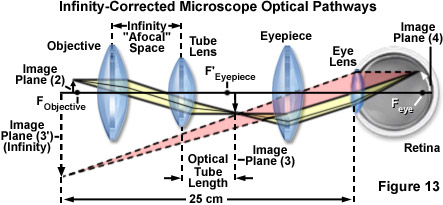
In summary, Ray paths through both finite tube length and infinity-corrected microscopes are reviewed and illustrated in Figures 12 and 13. A finite (fixed tube length) microscope optical train is illustrated in Figure 12, which includes the essential optical elements and ray traces defining the relationship between image planes. A specimen located a short distance before the objective front focal plane is imaged through conjugate planes onto the retina of the eye at Image Plane (4). The objective lens projects a real and inverted image of the magnified specimen into the intermediate image plane of the microscope (Image Plane (3)), which is located in the center of the eyepiece field diaphragm at a fixed distance behind the objective. In Figure 12, the objective rear focal plane is positioned at a location on the optical axis marked F'(Objective), and the distance between this focal plane and the intermediate image plane represents the optical tube length of the microscope.
| Interactive Tutorial |
|
||||||||||
|
|||||||||||
The aerial intermediate image is further magnified by the microscope eyepiece and produces an erect image of the specimen on the retina surface, which appears inverted to the microscopist. As discussed above, the magnification factor of the specimen is calculated by considering the distance between the specimen and the objective, and the front focal length of the objective lens system (F(Objective)). The image produced at the intermediate plane is further magnified by a factor of 25 centimeters (called the near distance to the eye) divided by the focal length of the eyepiece. The visual image (virtual) appears to the observer as if it were 10 inches away from the eye.
Most objectives are corrected to work within a narrow range of image distances, and many are designed to work only in specifically corrected optical systems with matching eyepieces. The magnification inscribed on the objective barrel is defined for the tube length of the microscope for which the objective was designed.
Illustrated in Figure 13 is the optical train, using ray traces, of an infinity-corrected microscope system. The components of this system are labeled in a similar manner to the finite-tube length system (Figure 12) for easy comparison. Here, the magnification of the objective is determined by the focal length of the tube lens. Note the infinity "afocal" space that is defined by parallel light beams in every azimuth between the objective and the tube lens. This is the space used by microscope manufacturers to add accessories such as vertical illuminators, DIC prisms, polarizers, retardation plates, etc., with much simpler designs and with little distortion of the image. The magnification of the objective in the infinity-corrected system equals the focal length of the tube lens divided by the focal length of the objective.
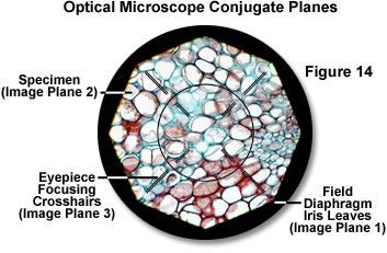
In the optical microscope, conjugate planes are imaged into each other and can collectively be observed while examining a specimen in the eyepieces. This concept is illustrated in Figure 14 with the image of a stained thin section of plant tissue superimposed on the iris leaves of the field diaphragm and a focusing reticle in the eyepiece intermediate image plane. The field iris diaphragm, adjacent to the lamp collector lens, is imaged sharply into the same plane as the specimen by the microscope condenser. Images of both the field diaphragm and the specimen are formed in the intermediate image plane by the objective and are projected into the fixed field diaphragm of the eyepiece, where the focusing reticle is located. Subsequently, the eyepiece (in conjunction with the observer's eye, located at Image Plane (4)) forms images of all three previous image planes on the sensor surface of an imaging system or the retina of a human eye. The field diaphragm, specimen, intermediate image, and retina all constitute a set of conjugate image planes that appear simultaneously in focus.
Contributing Authors
Kenneth R. Spring - Scientific Consultant, Lusby, Maryland, 20657.
Michael W. Davidson - National High Magnetic Field Laboratory, 1800 East Paul Dirac Dr., The Florida State University, Tallahassee, Florida, 32310.
BACK TO MICROSCOPE OPTICAL COMPONENTS
