
Max Berek
(1886-1949)
Max Berek was a German physicist and mathematician, associated with the firm of E. Leitz, who designed a wide spectrum of optical instruments, in particular for polarized light microscopy and several innovative camera lenses.
Professor Berek is credited as the inventor of the Leica camera lens system at their Wetzlar factory. He joined E. Leitz in 1912 and computed designs for the first Leica lens, the 50-millimeter Anastigmat (that later evolved into the four-element Elmax) and the five-element Elmar lens. Because of his refusal to comply with the Nazi regime demands, he was stripped of his professorship in the early 1940s, but was reinstated in 1946, three years before his death.
Originally a small microscope works, E. Leitz did not have the funds in the 1920s and 1930s to design camera lenses that could compete with the advanced models produced by Zeiss and Voigtlander. Berek employed several techniques in his designs to enhance the apparent performance by emphasizing out-of-focus softness. He also introduced three-point centering in 1920 for microscope objectives so that objects in the center of the field review remained in place after a new objective was rotated into the microscope optical path. Other innovations by the German lens maker include the tilting calcite (Berek Compensator) tunable waveplate, several early improvements in the development of the highly portable 35-millimeter camera (over large format cameras), and an anti-reflective coating for lenses. Berek's publications include the landmark 1930 Basis of the Practical Optics. Analysis and Synthesis of Optical Systems, Guidance for Optical Investigations with the Polarization Microscope (1953), and Mikroskopische Mineralbestimmung Mit Hilfe Der Universaldrehtischmethoden (1924).
Berek Compensator - An optical device that is capable of quantitatively determining the wavelength retardation of a crystal, fiber, plastic film or other birefringent material. Provided the thickness of the material can be measured, a Berek compensator can be utilized to ascertain the birefringence value.
Max Berek developed this style of polarization compensator in 1913 as a variable waveplate that can impose a quarter or half-wave retardation at any wavelength between 200 and 2800 nanometers, dramatically reducing the number of compensation plates necessary for quantitative polarized light microscopy. The compensator consists of a single cut plate of uniaxial birefringent material (calcite) having an extraordinary optical axis perpendicular to the long dimension of the plate frame. The calcite plate is tilted about the horizontal axis by means of a calibrated micrometer drum to enable precise measurements of retardation.
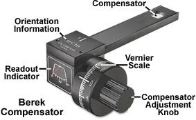
As illustrated in the figure above, the Berek compensator is equipped with a tilting calcite plate housed in a rectangular frame and controlled by a rotating drum knob affixed to a vernier scale. The compensator is positioned in the microscope intermediate tube at a 45-degree angle with respect to the polarization directions of the polarizer and analyzer, and the retardation is varied by turning the compensator knob.
In practice, a birefringent specimen (usually a crystal) is placed on the microscope stage and rotated until it attains the extinction position (where the features of interest become dark). Next, the stage is rotated +45-degrees and clamped into place. The compensator drum knob is set to a position of 30-degrees (turning the knob in a single direction to avoid backlash) and inserted into the microscope intermediate tube. Finally, the compensator knob is rotated to confirm that the black fringe intersects the center of the field of view. If the fringe does not intersect the center, the stage is rotated by 90-degrees and re-clamped. An interference filter having a transmission bandwidth between 540 and 570 nanometers will improve the accuracy of measurements, but also produces multiple black fringes in addition to the one that is visible in the absence of the filter. A reference table gives the optical path differences for the tilt angle in which compensation is achieved.