
Interference
When a film of oil floating atop a body of water reflects light, a swirling mass of colors seems to magically appear. Yet, even though many people have seen such a sight, few realize that the cause of this strange phenomenon is interference between light waves. A simple soap bubble, like the one shown in Figure 1, is another common example of interference, reflecting a variety of beautiful colors when illuminated by natural or artificial light sources.
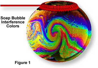
This dynamic interplay of colors is generated by the simultaneous reflection of light from both the inside and outside surfaces of the bubble. The two surfaces are very close together, but the light reflected from the inner surface of the bubble must still travel further than light reflected from the outer surface. When the waves reflected from the inner and outer surface combine they interfere with each other, removing or reinforcing some parts of white light, resulting in the appearance of color. If the extra distance traveled by the inner light waves is exactly the wavelength of the outer light waves, then when the waves combine constructive interference occurs and bright colors of those wavelengths are produced. In places where the waves are out of step, destructive interference transpires, canceling the reflected light and the color.
In order to better understand how light waves interfere with one another, consider a pair of light waves from the same source that are traveling in direction D, as illustrated below in Figure 2. If the vibrations, which are perpendicular to the propagation direction as represented by C, are parallel to each other and are also parallel with respect to the direction of vibration, then the light waves may interfere with each other. However, if the vibrations are not in the same plane or are vibrating at 90 degrees to each other, then they cannot interfere with one another.
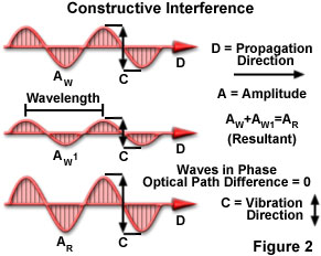
Assuming all of the criteria listed above are met, then the waves can interfere either constructively or destructively with each other. If the crests of one wave coincide with the crests of the other, the amplitudes of the waves are additive. Thus, if the amplitudes of both waves are equal, the resultant amplitude is doubled. It is important to remember, however, that light intensity varies directly as the square of the amplitude. Thus, if the amplitude of a light wave is doubled, its intensity is quadrupled. Such additive interference is demonstrated in Figure 2 and is known as constructive interference.
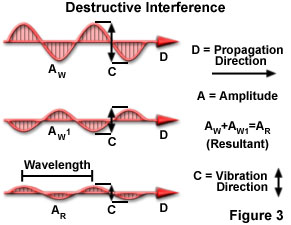
Alternatively, if the crests of one wave coincide with the troughs of the other wave, the resultant amplitude is decreased, as illustrated in Figure 3. This destructive interference is accompanied by a decrease in light intensity and may even result in complete blackness if a total cancellation of light waves occurs.
| Interactive Java Tutorial | |||||||||||
|
|||||||||||
Sir Isaac Newton, the famous seventeenth century mathematician and physicist, was one of the first scientists to study interference phenomena. In his famous Newton's rings experiment, he placed a convex lens of large curvature on a flat glass plate and applied pressure to hold the lens and glass plate together. When he viewed them through reflected sunlight, he observed a series of concentric light and dark colored bands similar to those illustrated in Figure 4. Although Newton recognized that the rings indicated the presence of some degree of periodicity in light, which would seem to suggest a wave theory, he primarily regarded light as a stream of particles, a commonly held opinion at the time.
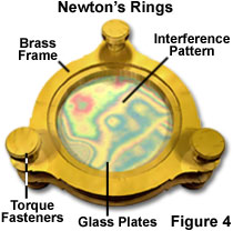
The rings occurred in Newton's experiment because of a thin layer of air that existed between the curved convex and flat glass surfaces. Light reflected from the top and bottom surfaces of the glass combined, producing interference patterns that appeared as the colored rings. Today, the basic principle of Newton's experiment is often used by lens manufacturers to test the uniformity of large polished surfaces.
During the early nineteenth century, general opinion continued to be in favor of the particle theory of light. However, an innovative physicist named Thomas Young found compelling evidence that supported the notion that light is a wave phenomenon. In 1801, he conducted an important experiment, often termed the double-slit experiment, which demonstrated interference in such a way that it could only be explained if visible light possessed wave-like properties.
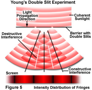
In his experiment, Young created a coherent light source by diffracting sunlight through a single slit. However, in Figure 5, in which the basic set-up of the double-slit experiment is illustrated, a coherent red laser acts as the light source. In this example, coherent laser light illuminates a barrier containing two small apertures and a screen is placed in the region behind the slits. As the light is diffracted through the apertures, each diffracted wave meets the other in a series of steps, or phases. When the waves meet in step, their amplitudes add together due to constructive interference and a bright area is displayed on the screen. In areas where the waves meet completely out of step, they subtract from each other due to destructive interference and a dark area appears in that portion of the screen. The resulting patterns on the screen, a product of interference between the two diffracted beams of laser light, are often referred to as interference fringes.
| Interactive Java Tutorial | |||||||||||
|
|||||||||||
Over the years, many other types of experiments have been devised to demonstrate the wave-like nature of light and interference effects. Most notable are the single mirror experiment of Lloyd and the double mirror and bi-prism experiments devised by Augustin Fresnel. These experiments are described in detail in many of the physics books listed in the Molecular Expressions bibliography.
Interference intensity distribution fringes, such as those observed in Young's double slit experiment, vary in intensity when they are presented on a uniform background. The visibility (V) of the intensity was defined in the early twentieth century by physicist Albert Michelson as the difference between the maximum and minimum intensity of a fringe divided by their sum, which may be mathematically represented as:
where I(max) is the maximum intensity and I(min) is the minimum intensity. Based on this equation, idealized fringe intensity always lies between zero and one. However, in practice, fringe visibility is dependent upon the geometrical design of the experiment and the spectral range used. Thus, a myriad of interference patterns can be observed in naturally occurring events.
In modern times, now that scientists have a clear understanding of how interference works, it is often utilized for a variety of purposes. For instance, with the help of lasers, interference can be used to measure very small distances over a range of many miles. This is accomplished by splitting a laser beam and reflecting it back from different surfaces. Analysis of the resulting interference fringes (upon recombining the separate laser beams) yields a remarkably accurate calculation of the distance between the two objects.
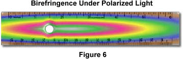
Interference patterns may also be used to test material condition, since colors arising from stressed regions in materials can be easily observed in polarized light. For example, the ruler in Figure 6 is made of plastic and is being observed through crossed polarizers. Under normal light, the ruler appears translucent and its graduations are plainly visible. However, when viewed under polarized light, the ruler exhibits stress patterns that appear more profound in areas that are more highly deformed. This is due to a high degree of alignment of the long-chain polymer molecules that comprise the ruler. Note that the greatest degree of interference occurs near the hole on the left side of the ruler.
Holography, a field first introduced in the 1940s, is yet another instance of the ability of humans to find practical uses for optical phenomena. In fact, holography is entirely dependent upon the interference of light to create its three-dimensional effects. In reflection holograms, both a reference and object-illuminating beam are reflected onto a thick film from opposite sides. These beams interfere to produce light and dark areas that correspond to an image that appears three-dimensional. Transmission holograms use both the reference and object-illuminating beams on the same side of the film to produce a similar type of effect.
Although interference is a characteristic behavior of light, it is not solely an optical phenomenon. Interference also occurs between sound waves, as well as waves induced in a standing pool of water. A very concise and easy interference experiment can be performed at home using a sink full of water and two marbles. First, let the water become very still, then simultaneously drop the marbles into the water (about 10-14 inches apart) from a height of about a foot. Just as with light waves, the two marbles will induce a series of waves in the water emanating in all directions. Waves formed in the area between the spaces where the marbles entered the water will eventually collide. Where they collide in step, they constructively add together to make a bigger wave and where they collide out of step they destructively cancel each other out.
Contributing Authors
Mortimer Abramowitz - Olympus America, Inc., Two Corporate Center Drive., Melville, New York, 11747.
Shannon H. Neaves and Michael W. Davidson - National High Magnetic Field Laboratory, 1800 East Paul Dirac Dr., The Florida State University, Tallahassee, Florida, 32310.