
Diffraction of Light
Classically, light is thought of as always traveling in straight lines, but in reality, light waves tend to bend around nearby barriers, spreading out in the process. This phenomenon is known as diffraction and occurs when a light wave passes by a corner or through an opening or slit that is the approximate size of, or even smaller than, that light's wavelength.
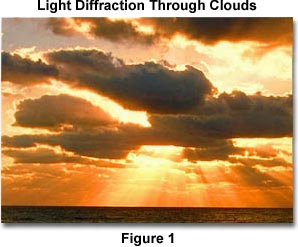
A very simple demonstration of diffraction can be conducted by holding one's hand in front of a light source and slowly closing two fingers while observing the light transmitted between them. As the fingers approach each other and come very close together, a series of dark lines parallel to the fingers begins to appear. The parallel lines are an example of diffraction patterns. This phenomenon can also occur when light is bent around particles that are on the same order of magnitude as the wavelength of the light. An example of such a situation is illustrated above in Figure 1, which exhibits the diffraction of sunlight by clouds during sunset, resulting in what is often referred to as their silver lining. Pastel shades of blue, pink, purple, and green are also observed at times in cloud cover and are generated when light is diffracted from water droplets within the clouds. The amount of diffraction that occurs depends on the wavelength of the light, and shorter wavelengths are diffracted at a greater angle than longer ones.
The image below further illustrates what happens when a light wave traveling through the atmosphere encounters a droplet of water. As demonstrated, the light is first refracted at the interface between air and water, and then it is reflected as it again encounters the interface. The beam, still traveling inside the water droplet, is then refracted once more as it strikes the interface for a third time. This last interaction with the interface refracts the light back into the atmosphere, but it also diffracts a portion of the light as illustrated below. This diffraction element leads to a phenomenon known as Cellini's halo, or the Heiligenschein effect, in which a bright ring of light surrounds the shadow of the observer's head.
The terms diffraction and scattering are often used interchangeably and are considered to be almost synonymous. However, diffraction describes a specialized case of light scattering in which an object with regularly repeating features, such as a diffraction grating, produces an orderly diffraction of light in a diffraction pattern. In the real world, most objects are very complex in shape and should be considered to be composed of many individual diffraction features that can collectively produce a random scattering of light.
One of the most classic and fundamental concepts of diffraction can be demonstrated by the single-slit optical diffraction experiment, first conducted in the early nineteenth century. That is, when a light wave propagates through a slit, the physical size of the aperture with respect to the wavelength of the incident beam determines how the light reacts. This same concept is illustrated below in Figure 2. As demonstrated on the left side of the figure, when the wavelength (l) is much smaller than the aperture width (d), the wave simply travels onward in a straight line, just as it would if it were a particle or no aperture were present.

The right side of Figure 2, however, illustrates a different situation. In this case, the wavelength of light transmitted by a point source exceeds the size of the aperture and light is diffracted, with the primary incident light beam landing at point P and the first secondary maxima occurring at point Q. Such a situation results in a diffraction pattern that consists of a bright central portion called the primary maximum flanked on both sides by secondary maxima, which are separated by dark sections known as minima. The secondary maxima decrease in intensity as their distance from the center, the area of highest intensity, increases. The relationship between the size of an aperture and the diffraction that occurs can be demonstrated through the equation:
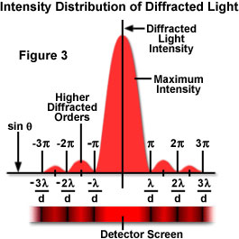
where q is the angle between the incident central propagation direction and the first minimum of the diffraction pattern. Below, Figure 3 further illustrates this point through a plot of beam intensity versus diffraction radius. Note that the minima occurring between secondary maxima are located in multiples of p.
The single-slit diffraction experiment was first explained by Augustin Fresnel who, along with Thomas Young, produced important evidence confirming that light travels in waves. Based on his findings, Fresnel assumed that the amplitude of the first order maxima at point Q (defined as eQ) would be given by the equation:
where A is the amplitude of the incident wave, r is the distance between d and Q, and f(c) is a function of c, an inclination factor introduced by Fresnel. It is important to note that both this Fresnel equation and the one related previously are only meant to describe the behavior of diffraction through an aperture in the shape of a slit.
| Interactive Java Tutorial | |||||||||||
|
|||||||||||
Nevertheless, circular apertures are extremely important to consider because all optical instruments have circular apertures. The pupil of an eye and the circular diaphragm and lenses of a microscope are testaments to this fact. Circular apertures produce diffraction patterns similar to those described previously, but the patterns naturally exhibit a circular symmetry. Mathematical analysis of the diffraction patterns produced by a circular aperture provides the equation:
where q(1) is the angular position of the first order diffraction minima (the first dark ring), l is the wavelength of the incident light, d is the diameter of the aperture, and 1.22 is a constant. Under most circumstances, the angle q(1) is very small, so the approximation that the sin and tan of the angle are almost equal yields:
From these equations it becomes apparent that the central maximum is directly proportional to l/d, making this maximum more diffuse for longer wavelengths and for smaller apertures.
Diffraction plays a paramount role in limiting the resolving power of any optical instrument. The resolving power is the optical instrument's ability to produce separate images of two adjacent points. No matter how perfect a lens may be, the image of a point source of light produced by the lens is accompanied by secondary and higher order maxima. This phenomenon could be eliminated only if the lens had an infinite diameter. Two objects separated by a distance less than q(1) cannot be resolved, no matter how high the power of magnification.
Therefore, it is important to realize that although the previous equations were derived for the image of a point source of light an infinite distance from the aperture, a reasonable approximation of the resolving power of a microscope may be obtained when d is substituted for the diameter of the objective lens. Consequently, if two objects reside a distance D apart from each other and are at a distance L from an observer, the angle (expressed in radians) between them is:
The previous two equations can then be condensed to yield:
where D(0) is the minimum separation distance between the objects that will allow them to be resolved. According to this equation, the human eye should be able to resolve objects separated by a distance of 0.056 millimeters. However, the photoreceptors in the retina are not quite close enough together to permit this degree of resolution and 0.1 millimeters is a more realistic number under normal circumstances.
The resolving power of optical microscopes is determined by a number of factors, such as optical alignment of the microscope, quality of the lenses, and the predominant wavelengths of light used to image the specimen. In the most ideal circumstances, the resolving power is about 0.2 micrometers. However, it is often not necessary to calculate the exact resolving power of each objective used, but it is important to understand the capabilities of microscope lenses as they apply to the real world.
Contributing Authors
Mortimer Abramowitz - Olympus America, Inc., Two Corporate Center Drive., Melville, New York, 11747.
Shannon H. Neaves and Michael W. Davidson - National High Magnetic Field Laboratory, 1800 East Paul Dirac Dr., The Florida State University, Tallahassee, Florida, 32310.