
Objective Properties
The Intel Play QX3 Computer Microscope has three objectives positioned in a rotating turret assembly to allow easy selection and changing of the microscope's magnification factor. Internal lens elements in the objectives are made with optical-grade plastic that has been molded and cut to the proper dimensions necessary to produce magnified images of specimens placed on the microscope stage.

Laws of geometrical optics assume that light travels along rays that are straight in a homogeneous medium, and are refracted by lenses before proceeding to form an image of the object being examined. Ray trace paths of light passing through each of the QX3 objectives are illustrated in Figure 1. These paths are based on calculations of the objective working distances and the approximate location of the rear focal planes. The QX3 microscope 10x objective, having the largest front lens, is illustrated in Figure 1(a) with three trace paths traveling through the objective. Likewise, Figure 1(b) and 1(c) trace ray paths for the 60x and 200x objectives, respectively.
Plastic Optics
The QX3 takes advantage of plastic lens technology to produce magnified images and project image data onto the surface of the CMOS active pixel sensor integrated circuit. Plastic optics have a number of advantages over glass. They have a much lower cost, a higher impact resistance, are of lighter weight, and have more configuration possibilities for simplifying system design and assembly. Modern plastic lenses have a light transmittance value that is comparable to high-grade crown glasses. These factors make plastic an ideal material for high volume optical instruments such as toy microscopes.
There are some disadvantages to plastic optical components. Primarily, plastic optics have a low tolerance to severe temperature fluctuations and they also have a low resistance to scratching. The QX3 microscope is not designed for temperature extremes and the lenses are protected from scratches by the microscope body housing and the front lens cover. Therefore, the primary disadvantages to using plastic optics do not directly apply the QX3.
Properties of Optical Plastics
|
||||||||||||||||||||||||||||||||||||||||||||||||||||
Objective lenses for the QX3 microscope are molded using polymethylmethacrylate (PMMA; similar to Plexiglas), a plastic that demonstrates a high degree of transmission in the visible absorption region. In fact, the transmittance of acrylic is higher than most optical glasses throughout the visible spectrum. The transmittance of a material is influenced by both reflection and absorption and is represented by the ratio of light transmitted through the material versus light that is incident upon the surface. PMMA is the hardest, most scratch-resistant and mechanically stable of all available optical plastic materials, and is used for greater than 80 percent of applications that employ plastic lenses (other than eyeglasses).
Other plastics useful in the production of optical components are polystyrene, polycarbonate, and PMMA/Styrene copolymers. Several of the useful optical properties of these polymers are listed in Table 1. Note that all polymers in Table 1 have a refractive index similar to or greater than that of optical glass.
The dispersion properties of optical plastics are listed according to their Abbe value, which has a tendency to decrease as the refractive index increases. In general, dispersion values of optical plastics is within the acceptable range for use in microscope optics. Birefringence, a problem with many plastics, is measured by the difference in refractive index of a material from light passing in two non-equivalent axes. In polymers, birefringence occurs as a result of stress, but is also a basic characteristic of other optically clear materials, including mica, quartz, and glass.
Objective Performance
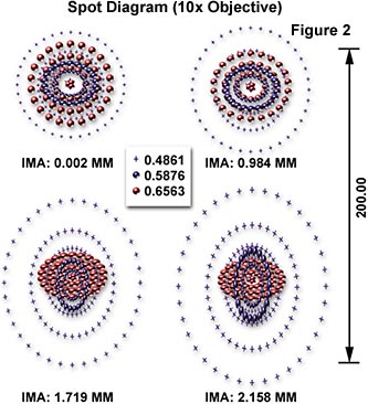
In order to determine whether an objective is sufficiently well corrected for a particular application, optical engineers will trace a large number of light rays from a point source of uniform intensity that fall in a distributed array over the vignetted entrance pupil of the objective. These points are then used to plot a Spot Diagram of points at which these rays pierce the image plane (Figure 2). Often, it is necessary to trace several hundred light rays before a realistic appearance of the point image can be obtained. Chromatic lens errors can be readily detected with the spot diagram method by tracing sets of rays having different wavelengths and measuring the spacing of the rays as they enter and exit the lens. The spot diagram illustrated in Figure 2 was constructed using polychromatic white light to generate a pattern for the Intel Play QX3 microscope 10x objective.
In order to interpret the spot diagram, it is often considered as a point spread function and is converted into a graph of modulation transfer function (MTF) plotted against spatial frequency. This is illustrated in Figure 3 for the QX3 microscope 10x objective where the MTF of a perfect lens (red plot) is compared to the actual values obtained with the QX3 microscope objective (colored plots). The MTF graph contains information about the resolving power of the objective in addition to information about image contrast generated by the objective. Computation of the MTF has now become a standard for comparing resolution and contrast in imaging optics using a single specification.
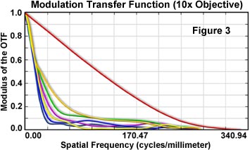
When a lens or a microscope objective images a sinusoidal pattern of varying intensity, such as a fine-lined micrometer grid or a periodic specimen, the resulting image will also have a sinusoidal variation with an increased spatial frequency dependent upon the spatial frequency of the object (grid or specimen) multiplied by the lens or objective magnification. As a result, contrast will be reduced and a phase shift may also occur, which can have a significant impact on the resolution of the lens or objective. The QX3 microscopes have a non-linear phase shift as a function of spatial frequency and this phenomenon affects image quality and contrast.
The spot diagrams and MTF curves for the QX3 microscope 60x and 200x objectives have also been measured and calculated. Follow the links below to navigate to this data for the QX3 microscope objectives.
10x Objective - Examine the ray trace pattern, spot diagram, and MTF curves for the QX3 microscope 10x objective.
60x Objective - Examine the ray trace pattern, spot diagram, and MTF curves for the QX3 microscope 60x objective.
200x Objective - Examine the ray trace pattern, spot diagram, and MTF curves for the QX3 microscope 200x objective.
Other properties of the QX3 microscope objectives, including the optical magnification, numerical aperture, focal length, and Airy disk diameters, are compiled in Table 2.
QX3 Objective Properties
|
||||||||||||||||||||||||||||||
Table 2
The optical magnification of the three objectives is modest and most image enlargement occurs digitally with the interactive software. It is necessary to maintain a low magnification for these objectives to ensure the greatest performance possible with limitations of the design and construction materials. Numerical apertures are also relatively low for the QX3 objectives, but this is to be expected with objectives of low magnification. The effective focal length is a function of objective design and is constrained by the optics in each objective.
In order for the microscope to perform properly in the hand-held mode, the objective working distances must all be similar. Empirical measurements of the QX3 objective working distances are listed in Table 2. All three objectives have practically identical working distances, which ensures that the protective body cowling shroud can act effectively as a guide to position the microscope for easy focus when it is removed from the base.
BACK TO INTEL PLAY QX3 MICROSCOPE ANATOMY
Questions or comments? Send us an email.
© 1995-2025 by Michael W. Davidson and The Florida State University. All Rights Reserved. No images, graphics, software, scripts, or applets may be reproduced or used in any manner without permission from the copyright holders. Use of this website means you agree to all of the Legal Terms and Conditions set forth by the owners.
This website is maintained by our
Graphics & Web Programming Team
in collaboration with Optical Microscopy at the
National High Magnetic Field Laboratory.
The QX3 microscope design is copyrighted © 2025 by Mattel, Inc. Intel® Play™ is a registered trademark of the Intel Corporation. These companies reserve all of their rights and privileges under copyright law. The material contained in this website is solely the opinion of the authors and is intended for eduational use only.
Last Modification Friday, Nov 13, 2015 at 02:18 PM
Access Count Since April 22, 2000: 46866
Visit the official Intel Play website:
![]()