
Resistance
Resistance refers to the property of a substance that impedes the flow of electric current. Some substances resist current flow more than others. If a substance offers very high resistance to current flow it is called an insulator. If its resistance to current flow is very low, it is called a conductor. Resistivity refers to the ability of substances to resist current flow. Good conductors have low resistivity and insulators have high resistivity.
Resistance at the Molecular LevelResistance to current flow occurs at the molecular level of substances. For example, a metal conductor, such as copper, consists of atoms having free electrons in their outer most shells. These free electrons ordinarily move randomly from one atom to another. However, if a potential difference, also called voltage, is applied across the conductor, such as with a battery, free electrons flow from the negative to the positive terminals of the battery. Electric current refers to the rate of flow of electric charge, which causes free electrons to flow.
As electrons move through the conductor, some collide with atoms, other electrons, or impurities in the metal. It is these collisions that cause resistance. The molecular makeup of a substance determines the number of collisions, or amount of resistance, to electron flow. Since the molecular makeup of copper provides for extremely low resistivity, it is often used as a conductor in electric circuits.
As electrons collide with atoms and other particles, the energy provided by the applied voltage is converted into heat. We make use of the energy generated by resistance in the heating elements of toasters, incandescent lamps, and space heaters.
Observe resistance at the molecular level with our Resistance Interactive Java Tutorial.
| Interactive Java Tutorial | |||||||||||
|
|||||||||||
Georg Simon Ohm (1789-1854), a German physicist, formulated the relationships among voltage, current, and resistance into what is referred to as Ohm's law:
The current in a circuit is directly proportional to the applied potential difference and inversely proportional to the resistance of the circuit.
The International Standard (SI) unit of resistance is the ohm, designated by the Greek letter W. One ohm of resistance is equal to the resistance of a circuit in which a potential difference of one volt produces a current of one ampere.
Mathematically Ohm's law is written as:
I = E/R
where I is current in amperes, E is the applied voltage (difference in potential) in volts, and R is resistance in ohms.
Therefore, voltage can be calculated using the formula:
E = I * R
Resistance can be calculated using the formula:
R = E/I
It is important to note that adjusting voltage or current cannot change resistance. Resistance in a circuit is a physical constant and can only be modified by changing components, exchanging resistors for those rated at more or fewer ohms, or by adjusting variable resistors.
Here is a memory aid to help remember these formulas:
Cover up the value you wish to solve for and the equation remains.
Discover the relationship among current, voltage, and resistance with our Ohm's Law Interactive Java Tutorial.
| Interactive Java Tutorial | |||||||||||
|
|||||||||||
Most of the resistance in circuits is found in components that do specific work, such as bulbs or heating elements, and in devises called resistors. Resistors are devises that provide precise amounts of opposition or resistance to current flow. Resistors are very common in electric circuits. They are used to provide specific resistivity to limit current and to control voltage in a circuit.
Types of ResistorsResistors come in a variety of values and types. The most common type is the fixed resistor. Fixed resistors have single values of resistance, which remain constant. There are also variable resistors that can be adjusted to vary or change the amount of resistance in a circuit.
The value of resistance of resistors is given in ohms. Resistors can have values from less than one ohm up to many millions of ohms.
Fixed ResistorsThe most common fixed resistor is the composition type. The resistance element is made of graphite, or some other form of carbon, and alloy materials. These resistors generally have resistance values that range from 0.1 W to 22 MW.
Another kind of fixed resistor is the wire wound type. The resistance element is usually made of nickel-chromium wire wound on a ceramic rod. These resistors generally have resistance values that range from 1 W to 100 kW.
Variable ResistorsVariable resistors are used to adjust the amount of resistance in a circuit. A variable resistor consists of a sliding contact arm that makes contact with a stationary resistance element. As the sliding arm moves across the element, its point of contact on the element changes, effectively changing the length of the element. The rating of a variable resistor is its resistance at its highest setting.
Variable resistors are also called rheostats or potentiometers. The resistance elements of rheostats are usually wire wound. They are most often used to control very high currents, such as in motors and lamps. Potentiometers generally have composition elements. They are used as control devices in radios, amplifiers, televisions, and electrical instruments.
Rating TolerancesThe actual resistance of a resistor may be greater or less than its indicated rating. The possible range of variance from the indicated rating is called its tolerance. Common tolerances for composition resistors are ±5, ±10, and ± 20 percent. Wire wound resistors usually have a tolerance of ±5 percent.
Resistor Rating Color CodeComposition resistors are color coded to indicate resistance values or ratings. The color code consists of various color bands that indicate the resistance values of resistors in ohms as well as the tolerance rating. The Resistor Rating Color Code Table below is used to identify the resistance rating of resistors.
|
||||||||||||||||||||||||||||||||||||||||||||||||||||||||||||||||||||||||
Resistor Rating Color Code Table
Composition resistors generally have four color bands. The color code is read as follows:
- First, look up the number values of the first two bands on the table and combine the two numbers.
- Then multiply this two digit number by the value of the 3rd band, the multiplier band.
- The resulting number is the resistance value of the resistor in ohms.
- The fourth band is the tolerance band. If the 4th band is gold, the resistor is guaranteed to be within 5% of the rated value. If the 4th band is silver, it is guaranteed to be within 10%. If there is no 4th band, the resistor is guaranteed to be within 20% of the rated value.
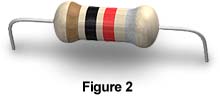
For example, the color code of the above resistor in Figure 2 is read as follows:
- The 1st band is brown. The first band is always the band closest to the end of the resistor. From the table you can see that the number value of brown in the 1st band column is 1.
- The 2nd band is black. The number value of black in the 2nd band column is 0.
- Combining the two numbers gives you 10.
- The 3rd band is red. This is the multiplier band. The multiplier value of red is 100.
- Multiplying the combined digit of 10 by the multiplier gives us 1,000.
Therefore, the above resister is rated at 1,000 ohms, which can be written as 1 kW. The 4th, or tolerance, band of the resister is silver. Therefore, the resistor is guaranteed to have a resistance value within 10% of 1kW.
Explore how resistors are color coded and observe the affect of resistance on current flow at our Resistor Color Code Interactive Java Tutorial.
| Interactive Java Tutorial | |||||||||||
|
|||||||||||
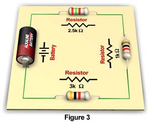
A series circuit is a circuit in which the current has only one path. In a series circuit, all of the current passes through each of the components in the circuit. The circuit below in Figure 3 has three resistors is series. The current from the battery flows through each of the resistors.
Since the current passes through each resistor in the circuit, the total resistance encountered by the current is cumulative. The same amount of resistance would exist in a circuit with a single resistor equal to the sum of the three resistors. Such a resistance is called the equivalent or total resistance of the circuit. The equivalent resistance of a series circuit is the sum of all the resistances in the circuit. Therefore, to calculate the total resistance of a series circuit, use the following formula:
RT = R1 + R2 + R3 . . .
where RT is the total or equivalent resistance in the circuit, and R1 through R3 . . . are the resistance ratings of the individual resistors or components in the circuit.
Using this formula, the total or equivalent resistance of the series circuit in Figure 3 can be calculated as follows:
RT = 2.5 + 1 + 3
RT = 6.5 kW
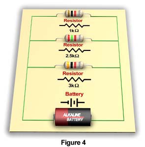
Resistors in Parallel CircuitsA parallel circuit is a circuit in which components are arranged so that the path for the current is divided. The circuit below in Figure 4 has three resistors in parallel.
Placing the resistors in parallel always decreases the total or equivalent resistance of the circuit. This is true because connecting resistors in parallel is equivalent to placing them side by side, increasing the total area available for the flow of current and thereby, reducing resistance. To calculate the total resistance of a parallel circuit, use the following formula:
where RT is the total resistance in the circuit, and R1 through R3 . . . are the resistance ratings of the individual resistors or components in the circuit.
Using this formula, the total or equivalent resistance of the above parallel circuit can be calculated as follows:
RT = 1 ÷ (1/1 + 1/2.5 + 1/3)
RT = 1 ÷ (1 + 0.4 + 0.33)
RT = 1 ÷ 1.73
RT = 0.58 kW
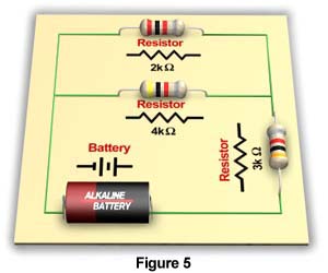
Circuits often consist of combinations of series and parallel circuits. These circuits are called compound circuits. The circuit in Figure 5 below is a compound circuit.
To calculate the total resistance of a compound circuit, first isolate and simplify all branches of the circuit to their equivalent resistances. The following steps are helpful:
- Calculate the equivalent resistances of resistors in parallel.
- Calculate the equivalent resistances of resistors in series.
- By repeating steps 1 and 2, as needed, the circuit can be simplified to an equivalent series circuit.
- Simply add the equivalent resistances of the simplified equivalent series circuit to find the total resistance of the compound circuit.
Using these steps, the total or equivalent resistance of the above parallel circuit can be calculated as follows:
First calculate the equivalent resistance of the two resistors in parallel:
RT = 1 ÷ (1/2 + 1/4)
RT = 1 ÷ (0.50 + 0.25)
RT = 1 ÷ 0.75
RT = 1.33 kW
At this point the circuit has been simplified to an equivalent series circuit consisting of an equivalent resistance of 1.33 kW and a resistance of 3 kW. Therefore, the total resistance of the compound circuit can be calculated as follows:
RT = 1.33 + 3
RT = 4.33 kW
Electric Power and ResistorsEven though electrons are very small, it takes energy to move them through a conductor. The energy available to move electrons is referred to as difference in potential, or voltage. Voltage is most often provided by a battery or generator. Voltage represents the work involved in the transfer of electric charge from one point to another. The higher the voltage, the more energy the current carries and the more work it can do.
In electric applications, voltage is often converted to other forms of energy to do work, such as heating, lighting, or motion. As noted earlier, we often make use of resistance to convert electric energy to heat or light.
The rate at which electricity does work or provides energy is referred to as electric power. The unit of electric power is the watt. One watt of power is delivered when a current of one ampere flows through a circuit whose voltage is one volt. Electric power can be calculated using the following formula:
P = I * E
where P is power in watts, I is current in amperes, and E is energy (applied voltage) in volts.
The wattage ratings of resistors indicate operating limits. The product of applied voltage and current through a resistor must not exceed its wattage rating. When current passes through a resistor, electric energy is converted to heat, which raises the temperature of the resistor. If the temperature becomes too high, the resistor may be damaged. The above electric power formula can be used to determine the maximum safe power consumption and appropriate wattage rating of a resistor to use for an application.
Power Ratings of ResistorsThe power rating of resistors is specified in watts. Composition type resistors have wattage ratings from 1/16 to 2 watts. Wire wound resistors have ratings from 3 watts to hundreds of watts. The size of the resistor is usually a good indicator of its power rating. Generally, the physical size of a resistor increases as the power rating increases.
Effect of Temperature on ResistivityThe resistivity of most materials changes with temperature. For most materials, resistance increases as the temperature of the material increases. This occurs at the molecular level. As electrons move through the material, some collide with atoms, other electrons, or impurities. It is these collisions that cause resistance. Heat causes molecules of the material to vibrate. These vibrations effectively increase the areas of possible collisions, thereby increasing resistance to current flow.
Most conductors increase in resistivity as temperature increases. Carbon however, decreases in resistivity as temperature increases. This is also generally true for semiconductors, such as germanium and silicon. The resistivity of constantan is not affected by changes in temperature. For this reason, constantan is often used for precision wire-wound resistors with very low tolerances.
Resistance and SuperconductivityFor most conductors, resistivity decreases as temperature decreases. For some materials, like mercury and aluminum, resistivity falls to zero at extremely low temperatures. Near absolute zero, -273°C, these materials are capable of carrying current without any resistance at all. These materials are called superconductors. The benefit of superconductors is that they can carry large quantities of current without any loss of energy to heat.
Superconducting materials are currently used in particle accelerators and other applications that require powerful electromagnets. Magnetic resonance imaging technology (MRI), powered with the use of superconductors, has revolutionized materials science and medicine. Superconductivity would be especially useful for the transmission of electric power. Currently, about 15 percent of electric power passing through copper transmission lines is lost as a result of resistance.
Unfortunately, it is very costly to cool superconductors to the critical temperatures required. Refrigeration units using liquid helium or liquid nitrogen are currently necessary to cool superconducting materials. However, progress is being made to increase temperatures required for superconductivity. Materials have already been developed that become superconducting at -175°C.
Scientists are working diligently to develop room-temperature superconductors. Such superconductors would greatly reduce the cost of electric power production and transmission. Electric motors could be made that are much smaller and powerful. Computers could be made even smaller and faster. Other amazing applications, such as magnet-levitated trains and launching of spacecraft, would become much more feasible.
See full color photomicrographs of superconducting materials at our Superconductor Collection of the Molecular Expressions Photo Gallery.
Learn more about superconductors at our Molecular Expressions Microscopy Publications site.
BACK TO ELECTRICITY AND MAGNETISM HOME