
Inductance
Inductance is a property of an electric circuit by which a changing magnetic field creates an electromotive force, or voltage, in that circuit or in a nearby circuit. Inductance is also defined as the property of an electric circuit that opposes any change in current. In 1831, Michael Faraday, an English scientist, discovered that a changing magnetic field in a circuit induced a current in a nearby circuit. Joseph Henry, an American scientist, independently made this discovery at about the same time. The generation of an electromotive force and current by a changing magnetic field is called electromagnetic induction. The operation of electric generators is based on the principal of inductance.
Magnetic Field LinesIn order to better understand inductance, it is helpful to have an understanding of magnetic field lines. All magnets are surrounded by a magnetic field, also called magnetic flux. A magnetic field can be thought of consisting of lines of force, or flux lines. The forces of magnetic attraction and repulsion move along the lines of force. The pattern of magnetic field lines can be observed in our Magnetic Field Lines Interactive Java Tutorial.
| Interactive Java Tutorial | |||||||||||
|
|||||||||||
Faraday made his discovery of electromagnetic induction with an experiment using two coils of wire wound around opposite sides of a ring of soft iron similar to the experiment setup in Figure 1 below.
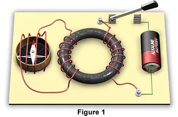
The first coil on the right is attached to a battery. The second coil contains a compass, which acts as a galvanometer to detect current flow. When the switch is closed, a current passes through the first coil and the iron ring becomes magnetized. When the switch is first closed, the compass in the second coil deflects momentarily and returns immediately to its original position. The deflection of the compass is an indication that an electromotive force was induced causing current to flow momentarily in the second coil. Faraday also observed that when the switch is opened, the compass again deflects momentarily, but in the opposite direction.
Faraday was aware that that a coil of wire with an electric current flowing through it generates a magnetic field. Therefore, he hypothesized that a changing magnetic field induces a current in the second coil. The closing and opening of the switch cause a magnetic field to change: to expand and collapse respectively. You can conduct Faraday's experiment at our Faraday's Experiment Interactive Java Tutorial.
| Interactive Java Tutorial | |||||||||||
|
|||||||||||
Faraday demonstrated that his hypothesis was correct by moving a simple bar magnet back and forth inside a coil. He observed that a current was induced in the coil only while the magnet was in motion. He also observed that a current was induced in the coil when the coil itself was moved near a stationary permanent magnet. He discovered that it is the relative motion between a conductor and a magnetic field that produces current. To generate current, either the conductor can move through the field, or the field can move past a conductor. In order for electromagnetic induction to occur, there must be a change of magnetic flux. Conduct this experiment at our Faraday's 2nd Experiment Interactive Java Tutorial.
| Interactive Java Tutorial | |||||||||||
|
|||||||||||
The relationship between changing magnetic flux and induced electromotive force is known as Faraday's law of electromagnetic induction:
The magnitude of an electromagnetic force induced in a circuit is proportional to the rate of change of the magnetic flux that cuts across the circuit.
Mathematically, Faraday's law is written as:
E = - (DF/Dt)
where E is the induced electromotive force in volts, DF is the change in magnetic force in webers, and Dt is the amount of time in seconds in which the change in magnetic force takes place.
From the above formula we see that the amount of induced voltage is determined by two factors:
- The amount of magnetic flux
The greater the number of magnetic field lines cutting across the conductor, the greater the induced voltage. - The rate at which the magnetic field lines cut across the conductor
The faster the field lines cut across a conductor, or the conductor cuts across the field lines, the greater the induced voltage. You can observe this by varying the speed at which you move the magnet in our Faraday's 2nd Experiment Interactive Java Tutorial.
The minus sign in Faraday's law refers to the direction, or polarity, of the induced voltage. In 1833, the Russian physicist Heinrich Lenz discovered the directional relationships among the forces, voltages, and currents of electromagnetic induction. Lenz's law states:
An induced electromotive force generates a current that induces a counter magnetic field that opposes the magnetic field generating the current.
For example, when an external magnetic field approaches a ring shaped conductor, the current that is produced in the ring will induce its own magnetic field in opposition to the approaching external magnetic field. On the other hand, when the external magnetic field moves away from the ring, the induced magnetic field in the ring reverses direction and opposes the change in the direction of the external magnetic field. You can observe Lenz's law in action at our Lenz's Law Interactive Java Tutorial.
| Interactive Java Tutorial | |||||||||||
|
|||||||||||
We know that current flow in a conductor produces a magnetic field around the conductor. When the current is increasing, decreasing, or changing direction, the magnetic field changes. The magnetic field expands, contracts, or changes direction in response to the changes in current flow. A changing magnetic field induces an additional electromotive force, or voltage in the conductor. The induction of this additional voltage is called self-induction, because it is induced within the conductor itself. The direction of the self-induced electromotive force, or voltage, is in the opposite direction of the current flow that generated it. This is consistent with Lenz's law, which can be expressed as follows:
An induced electromotive force (voltage) in any circuit is always in a direction in opposition to the current that produced it.
The effect of self-induction in a circuit is to oppose any change in current flow in the circuit. For example, when voltage is applied to a circuit, current begins to flow in all parts of the circuit. This current induces a magnetic field around it. As the field is expanding, a counter voltage, sometimes called back voltage, is generated in the circuit. This back voltage causes a current flow in the opposite direction of the main current flow. Inductance at this stage acts to oppose the buildup of current. When the induced magnetic field becomes steady, it ceases to induce back voltage.
When the current in a circuit is switched off, the induced magnetic field begins to collapse. As the field is collapsing, it generates voltage in the direction that momentarily prolongs the main current flow. When the induced magnetic field is fully collapsed, the induced voltage and current flow cease. Again, self-induction opposes changes in current flow. It opposes the buildup, and delays the breakdown, of current. You can see the effects of self-inductance on current flow in our Self-Inductance Interactive Java Tutorial.
| Interactive Java Tutorial | |||||||||||
|
|||||||||||
In Faraday's experiment with two coils on a conducting iron ring, he discovered that a changing magnetic field in one coil induces an electromotive force, or voltage, in the second coil. This phenomenon is called mutual inductance. Mutual inductance occurs when a changing magnetic field in one circuit induces voltage in a nearby circuit.
Consistent with Lenz's law, the direction of the induced electromotive force, or voltage, is in the opposite direction of the current flow that generated it. Looking at Faraday's experiment again below, we find that when voltage is applied to the coil on the right, a magnetic field is induced in the iron ring. As the field is expanding, a voltage is generated in the second coil on the left. This secondary voltage causes a current flow in the second coil. This secondary current flow is in the opposite direction of the current flow of the first coil. When the induced magnetic field in the ring becomes steady, current ceases to flow in the second coil.
When the current in the first coil is switched off, the induced magnetic field in the ring begins to collapse. As the field is collapsing, it again generates voltage in the second coil. The resulting current flow in the second coil is in the opposite direction of the previously induced current. When the magnetic field in the ring is fully collapsed, the induced voltage and current flow in the secondary coil ceases. You can conduct this experiment at our Faraday's Experiment Interactive Java Tutorial.
| Interactive Java Tutorial | |||||||||||
|
|||||||||||
Inductors are electric devices that are designed to provide inductance in a circuit. An inductor is simply a coil of wire. Self-inductance occurs in a circuit even when conductors are perfectly straight. However, self-inductance in a straight conductor is very small. Inductance is much more significant when conductors are coiled, because the magnetic field of each turn of the coil cuts across nearby turns of the coil. To increase inductance, an inductor may have an iron core. Putting iron inside a coil greatly increases the strength of its magnetic fields.
Factors Affecting Inductance of a CoilThe inductance of a coil is affected by three factors:
- The number of turns in the coil
The greater the number of turns in a coil, the greater the inductance. This is true because the more turns there are in a coil, the greater the number of magnetic field interactions. - The area of the cross section of the coil
The greater the cross-sectional area of a coil, the greater the inductance. This factor is closely related to the number of turns in a coil. It includes consideration of the spacing of the turns. Since a magnetic field becomes weaker as it moves out, turns that are closely spaced provide for interactions where the fields are strongest. - The permeability of the core
Permeability refers to the ability of a material to conduct magnetic lines of force. Iron has much greater permeability than air. Therefore, a coil with an iron core has greater inductance than one with a core containing just air.
Faraday's Law can be used to determine the total induced electromotive force, or voltage, in a coil. Assuming that the turns of the coil are closely wound, the total inducted voltage of a coil can be calculated using the following formula:
E = - N (DF/Dt)
where E is the induced electromotive force in volts, N is the number of turns in the coil, DF is the change in magnetic force in webers, and Dt is the amount of time in seconds in which the change in magnetic force takes place.
Measurement of InductanceThe symbol for Inductance is the capital letter L in honor of Heinrich Lenz. The unit of measurement for inductance is the henry, named after Joseph Henry, and abbreviated as h. One henry of inductance exists when one volt of electromotive force is induced when the current is changing at the rate of one ampere per second. Mathematically, this is written as:
L = E/(DI/Dt)
where L is inductance in henries, E is induced electromotive force in volts, DI is the change in current in amperes, and Dt is the amount of time in seconds in which the change in current takes place.
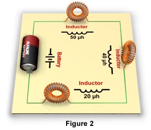
Inductors in Series CircuitsA series circuit is a circuit in which the current has only one path. In a series circuit, all of the current passes through each of the components in the circuit. The circuit in Figure 2 has three inductors in series.
If the inductors are shielded, or far enough apart to prevent mutual inductance, the total inductance of the circuit is cumulative. The total inductance of such a circuit is the sum of all the inductors in the circuit. Therefore, use the following formula to calculate the total inductance of a series circuit:
LT = L1 + L2 + L3 . . .
where LT is the total inductance in the circuit, and L1 through L3 . . . are the inductance ratings of the individual inductors in the circuit.
Using this formula, the total inductance of the series circuit in Figure 2 can be calculated as follows:
LT = 50 + 40 + 20
LT = 110 mh
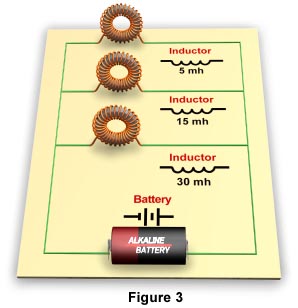
Inductors in Parallel CircuitsA parallel circuit is a circuit in which components are arranged so that the path for the current is divided. The circuit in Figure 3 has three inductors in parallel.
Placing inductors in parallel always decreases the total inductance of the circuit. If the inductors are shielded, or far enough apart to prevent mutual inductance, the total inductance of the circuit can be calculated using the following formula:
LT = 1 ÷ (1/L1 + 1/L2 + 1/L3 . . .)
where LT is the total Inductance in the circuit, and L1 through L3 . . . are the inductance ratings of the individual inductors in the circuit.
Using this formula, the total or inductance of the above parallel circuit can be calculated as follows:
LT = 1 ÷ (1/5 + 1/15 + 1/30)
LT = 1 ÷ (0.2 + 0.066 + 0.033)
LT = 1 ÷ 0.299
LT = 3.344 mh
The effect of self-induction in a coil is to oppose any change in current flow in the coil. For example, when voltage is applied to a coil, current begins to flow in the coil. This current induces a magnetic field around it. As the field is expanding, a counter voltage, sometimes called back voltage, is generated in coil. This back voltage opposes the main current flow. This opposition to current flow is called inductive reactance and is measured in ohms.
The amount of inductive reactance in a circuit depends on the frequency and amount of alternating current, and the amount of inductance. Inductive reactance of a circuit can be calculated using the following formula:
XL = 2pfL
where XLis inductive reactance in ohms, 2p is a calculus-derived constant that is normally rounded off to 6.28, f is the frequency of the applied alternating current in hertz, and L is the inductance of the circuit in henries.
TransformersThe operation of transformers is based on the principal of mutual inductance. Transformers are used to increase or decrease alternating current (AC) voltages and currents in circuits. A transformer usually consists of two coils of wire, electrically insulated from each other, wound on the same core. One coil is called the primary coil; the other is called the secondary coil. The primary coil is the input coil of the transformer and the secondary coil is the output coil. When an AC voltage is applied across the primary coil, it induces a changing magnetic field in the core. Mutual induction causes voltage to be induced in the secondary coil.
The number of windings of the primary and secondary coils of a transformer determines how the voltage in the circuit is affected. When the number of windings of the primary coil is greater than that of the secondary coil, the induced voltage in the secondary coil is less than the applied voltage of the primary coil. When the number of windings of the primary coil is less than that of the secondary coil, the induced voltage in the secondary coil is greater than the applied voltage of the first coil. If the output voltage of a transformer is greater than the input voltage, it is called a step-up transformer. If the output voltage of a transformer is less than the input voltage it is called a step-down transformer. Discover the effects of varying voltage inputs and number of windings of a transformer in our Transformer Interactive Java Tutorial.
| Interactive Java Tutorial | |||||||||||
|
|||||||||||
A step-up transformer increases voltage. However, the increase in voltage comes with a decrease in current. The opposite is true for a step-down transformer. A step-down transformer reduces voltage but increases current. This property of transformers makes them very useful and beneficial for transmitting electric power over long distances. Step-up transformers are used at electric power generating plants to develop very high voltages. The output current flow is reduced, which greatly reduces the losses in power due to resistance in transmission lines. When the power reaches consumers, step-down transformers are used to reduce voltage and increase current to appropriate levels for consumer applications.
Applications of InductanceThe properties of inductors make them very useful in various applications. For example, inductors oppose any changes in current. Therefore, inductors can be used to protect circuits from surges of current. Inductors are also used to stabilize direct current and to control or eliminate alternating current. Inductors used to eliminate alternating current above a certain frequency are called chokes.
GeneratorsOne of the most common uses of electromagnetic inductance is in the generation of electric current. To learn how a generator works visit our Generators and Motors Primer.
Radio ReceiversInductors can be used in circuits with capacitors to generate and isolate high-frequency currents. For example, inductor coils are used with capacitors in tuning circuits of radios. In Figure 4, a variable capacitor is connected to an antenna-transformer circuit. Transmitted radio waves cause an induced current to flow in the antenna through the primary inductor coil to ground.
A secondary current in the opposite direction is induced in the secondary inductor coil. This current flows to the capacitor. The surge of current to the capacitor induces a counter electromotive force. This counter electromotive force is call capacitive reactance. The induced flow of current through the coil also induces a counter electromotive force. This is called inductive reactance. So we have both capacitive and inductive reactances in the circuit.
At higher frequencies, inductive reactance is greater and capacitive reactance is smaller. At lower frequencies the opposite is true. A variable capacitor is used to equalize the inductive and capacitive reactances. The condition in which the reactances are equalized is called resonance. The particular frequency that is isolated by the equalized reactances is called the resonant frequency.
A radio circuit is tuned by adjusting the capacitance of a variable capacitor to equalize the inductive and capacitive reactance of the circuit for the desired resonant frequency, or in other words, to tune in the desired radio station. Our Radio Receiver Interactive Java Tutorial demonstrates how inductor coils and a variable capacitor are used to tune in radio frequencies.
| Interactive Java Tutorial | |||||||||||
|
|||||||||||
The operation of a metal detector is based upon the principle of electromagnetic induction. Metal detectors contain one or more inductor coils. When metal passes through the magnetic field generated by the coil or coils, the field induces electric currents in the metal. These currents are called eddy currents. These eddy currents in turn induce their own magnetic field, which generates current in the detector that powers a signal indicating the presence of the metal. Observe the magnetic fields and eddy currents generated by a metal detector at our Metal Detector Java Tutorial.
| Interactive Java Tutorial | |||||||||||
|
|||||||||||
BACK TO ELECTRICITY AND MAGNETISM HOME