
Generators and Motors
Magnets are pieces of metal that have the ability to attract other metals. Every magnet has two poles: a north and a south. Much like electrical charges, two similar magnetic poles repel each other; while opposite magnetic poles attract each other. Magnets have a continuous force around them that is known as a magnetic field. This field enables them to attract other metals. Figure 1 illustrates this force using bar and horseshoe magnets.
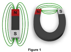
The shape of the magnet dictates the path the lines of force will take. Notice that the force in Figure 1 is made up of several lines traveling in a specific direction. It can be concluded that the lines travel from the magnet's north pole to its south. These lines of force are often called the magnetic flux. If the bar magnet is now bent to form a horseshoe magnet, the north and south pole are now across from each other. Notice in the horseshoe magnet how the lines of force are now straight, and that they travel from the north pole to the south. It will be revealed how generators and motors use these lines of force to generate electricity, as well as mechanical motion.
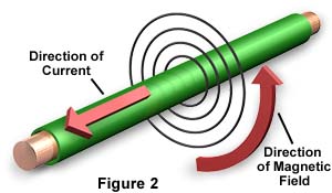
Magnetic Fields Around ConductorsWhen a current flows through a conductor, a magnetic field surrounds the conductor. As current flow increases, so does the number of lines of force in the magnetic field (Figure 2).
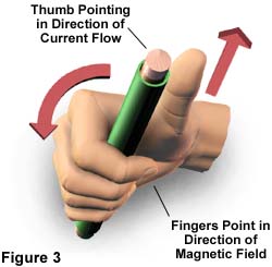
The right hand rule helps demonstrate the relationship between conductor current and the direction of force. Grasp a wire conductor in the right hand, put your thumb on the wire pointing upward, and wrap your four fingers around the wire. As long as the thumb is in the direction that current flows through the wire, the fingers curl around the wire in the direction of the magnetic field. Figure 3 demonstrates the right hand rule.
A conductor can be twisted into a coil, which efficiently produces current when cutting the lines of force in a magnetic field. The more turns in this coil, the stronger the magnetic field. Furthermore, if the coil is wrapped around a piece of iron, the current becomes even stronger.
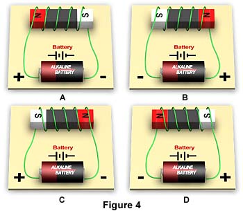
When needing to discover which poles are which in a conductor, it is important to notice which way the coils turn in order to apply the right hand rule. In addition, one should always look at which side of the coil is attached to the positive terminal of a power source such as a battery, and which side is attached to the negative. Figure 4 illustrates four different scenarios and the appropriate poles.
As a conductor cuts across the lines of force in a magnetic field, it generates a current. This method of inducing a current is called induction. There are three rules for induction:
- When a conductor cuts through lines of force, it induces an electromotive force (EMF), or voltage.
- Either the magnetic field or the conductor needs to be moving for this to happen.
- If the direction of the cutting across the magnetic field changes, the direction of the induced EMF also changes.
Accordingly, Faraday's law states that induced voltage can be determined by the number of turns in a coil, and how fast the coil cuts through a magnetic field. Therefore, the more turns in a coil or the stronger the magnetic field, the more voltage induced.
In addition, current changes direction depending on which way it cuts across a magnetic field. As depicted in Figure 5, a coil cutting through a basic magnetic field in a clockwise direction will at first result in a current with positive polarity, but as it cuts across the same field in the opposite direction during the second half of its turn, the polarity becomes negative.

When current switches from positive to negative repeatedly, it is called alternating current, or A.C. Alternating current will be explained in more detail later.
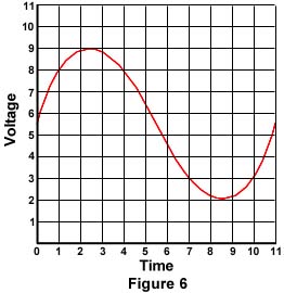
DC CurrentWhen a current is direct (D.C.) rather than alternating (A.C.), the polarity of that current never changes direction. Usually, when a coil turns in a clockwise direction, the first 180 degrees of the turn result in the induced current going in a positive direction. As mentioned above, however, the second 180 degrees result in the induced current going in a negative direction. In direct current, the current always travels in a positive direction. How is this possible? When inducing direct current, some mechanism must be employed to make sure the coils only cut through the magnetic field in one direction, or that the circuit only uses current from the coil cutting in that one direction. Devices such as D.C. generators employ a mechanism called a commutator to keep current flowing in one direction. Figure 6 shows direct current in the form of a sine wave. Notice that the current never has negative polarity, and is therefore always flowing in a positive direction.
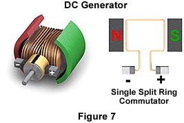
A generator is a device that turns rotary mechanical energy into electrical energy.
Simple D.C. generators contain several parts, including an armature (or rotor), a commutator, brushes, and field winding. A variety of sources can supply mechanical energy to the D.C. generator to turn its armature. The commutator changes the alternating current (A.C.) into direct current as it flows through the armature.
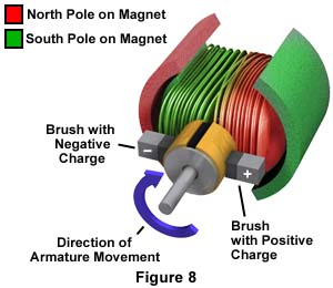
The stationary brushes, which are graphite connectors on the generator, form contact with opposite parts of the commutator. As the armature coil turns, it cuts across the magnetic field, and current is induced. At the first half turn of the armature coil (clockwise direction), the contacts between commutator and brushes are reversed, or to put it another way, the first brush now contacts the opposite segment that it was touching during the first half turn while the second brush contacts the segment opposite the one it touched on the first half turn. By doing this, the brushes keep current going in one direction, and deliver it to and from its destination.
Direct Current MotorsMotors change electric energy into mechanical energy. Direct current motors and generators are constructed very similarly. They function almost oppositely at first because a generator creates voltage when conductors cut across the lines of force in a magnetic field, while motors result in torque-- a turning effort of mechanical rotation. Simple motors have a flat coil that carries current that rotates in a magnetic field. The motor acts as a generator since after starting, it produces an opposing current by rotating in a magnetic field, which in turn results in physical motion.
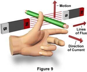
This is accomplished as a conductor is passed through a magnetic field, then the opposing fields repel each other to cause physical motion. The left hand rule can be used to explain the way a simple motor works (Figure 9). The pointer finger points in the direction of the magnetic field, the middle finger points in the direction of the current, and the thumb shows which way the conductor will be forced to move.
A self-excited motor produces its own field excitation. A shunt motor has its field in parallel with the armature circuit, and a series motor is when the field is in a series with the armature.
When the conductor is bent into a coil, the physical motion performs an up and down cycle. The more bends in a coil, the less pulsating the movement will be. This physical movement is called torque, and can be measured in the equation:
T = kt Q ia
T = torque
kt = constant depending on physical dimension of motor
Q = total number of lines of flux entering the armature from one N pole
ia = armature current
Alternating CurrentMuch like the process of producing direct current, the process of producing an alternating current requires a conductor loop spinning in a magnetic field. As a matter of fact, the process is the same for both types of current, except that the alternating current is never changed into direct current through the use of a commutator. The conductor loop, or coil, cuts through lines of force in a magnetic field to induce A.C. voltage at its terminals. Each complete turn of the loop is called a "cycle." The alternating current wave is pictured in Figure 10.
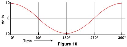
Notice what segment of the wave consists of one cycle, and which is the part of the wave from point A to the next point A. If we divide the wave into four equal parts, the divisions happen at points A, B, C, and D. We can read the turn of the coil and how it relates to the wave produced. From A to B is the first quarter turn of the coil, from B to C is the second quarter turn, from C to D is the third quarter turn, and from D to A is the final quarter turn.
It is important to note that degree markings on a horizontal axis refer to electrical degrees and are not geometric. The example above is for a single pole generator. However, if this were a double pole generator, then 1 cycle would happen at each 180 degrees rather than 360 degrees, and so on.
Alternating Current GeneratorAn alternating current generator, or alternator, produces an alternating current, which means the polarity of the current changes direction repeatedly. This type of generator requires a coil to cut across a magnetic field, and is attached to two slip rings connected to brushes. The brushes deliver the current to and from the load destination, thus completing the circuit.

During the first half turn, the coil cuts across the field near the magnet's north pole. Electrons go up the wire, and the lower slip ring becomes positively charged. When the coil cuts near the south pole of the wire during the second half turn, the lower slip ring becomes negatively charged, and electrons move down the wire. The faster the coil turns, the faster the electrons move, or to put it another way, the more frequency is increased, or the more hertz per second, the stronger the current.
Alternating Current MotorAn alternating current motor is similar to the direct current motor except for a few characteristics. Instead of the rotor field reversing every half turn, the stator field reverses every half turn.
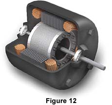
There are several different types of alternating current motors. The most common type is the polyphase induction motor, which contain a stator and a rotor, where the stator is attached to the A.C. supply. When the stator winding becomes energized, a rotating magnetic field is created. An EMF is induced as the field goes across the inductors and current flows through them. Torque is therefore exerted on the rotor conductors carrying current in the stator.
BACK TO ELECTRICITY AND MAGNETISM HOME