
An Introduction to Capacitance
Capacitance is the property of an electric conductor that characterizes its ability to store an electric charge. An electronic device called a capacitor is designed to provide capacitance in an electric circuit by providing a means for storing energy in an electric field between two conducting bodies.
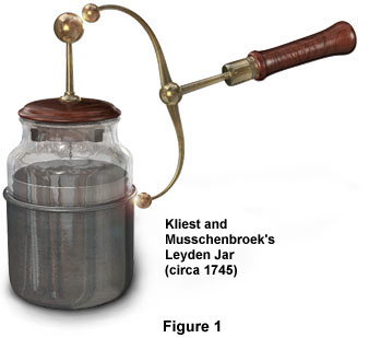
Around 1745, Ewald Christian von Kliest and Pieter van Musschenbroek independently discovered capacitance in an electric circuit. While engaged in separate studies of electrostatics, they discovered that an electric charge could be stored for a period of time. They were using a device now called a Leyden jar that consisted of a stoppered glass jar filled with water with a nail piercing the stopper and dipping into the water. They connected the nail to an electrostatic charge. After disconnecting the nail from the source of the charge they found that a shock could be felt by touching the nail. This demonstrated that the device had stored the charge.
In 1747 John Bevis refined the device further by replacing the water in the jar with metal foil. He lined both the inside and outside of the jar with the foil. This created a capacitor with two conductors (the inside and outside metal foil layers) equally separated by the insulating glass. These design features are incorporated into the modern capacitor. The Leyden jar was also used by Benjamin Franklin to store the charge from lightning and in other experiments. In fact, the natural phenomenon of lightning includes capacitance in that huge electric fields develop between cloud layers, or between clouds and the earth, prior to a lightning strike. We have constructed a Java tutorial that demonstrates this phenomenon.
| Interactive Java Tutorial | |||||||||||
|
|||||||||||
Capacitors are used in many ways in electronic circuits, such as barriers to direct currents, storing memory in a computer chip, storing a charge for an electronic flash camera, or adjusting a tuned circuit such as in a radio.
Description of a CapacitorA capacitor in its simplest form consists of two conducting plates separated by an insulating layer called a dielectric. When a capacitor is connected in a circuit across a voltage source, the voltage forces electrons onto the surface of one plate and pulls electrons off the surface of the other plate resulting in a potential difference between the plates. Capacitors are charged and discharged as needed by its application. Capacitors differ in size and arrangements of plates and the type of dielectric materials used. Paper, ceramic, air, mica, and electrolytic materials can be used, depending on the type of dielectric needed. The capacitance of a capacitor may be fixed or adjustable (as in a radio tuner).
Charging of a CapacitorWhen a capacitor is connected across a voltage source, such as a battery, the voltage forces electrons onto one plate resulting in a negatively charged plate. The electrons of the other plate are pulled off by the battery resulting in a positively charged plate. Because the dielectric between the plates is an insulator, current cannot flow through it. A capacitor has a finite amount of capacity to store charges. When a capacitor reaches its capacity it is fully charged.
The following diagrams illustrate the charging of a capacitor. Figure 2 shows a circuit containing a conductor connecting a battery, an open switch, and a capacitor. The capacitor in Figure 2 is not charged. There is no potential difference between the plates.

When the switch is closed, as in Figure 3, there is a momentary surge of current through the conductor to and from the plates of the capacitor. When the current reaches the negative plate of the capacitor, it is stopped by the dielectric.
The surge of electric current to the capacitor induces a counter electromotive force in the conductor and the plates. This counter electromotive force is call reactance. When reactance has reached a level equal to the voltage of the battery, the capacitor is fully charged. There is no further flow of current. When the capacitor is fully charged, the switch may be opened and the capacitor will retain its charge (Figure 4). Because of the difference of charges on the plates there is a source of potential energy in the capacitor. The energy stored is the energy that was required to charge the capacitor.
The lines of force between the plates of the capacitor represent an electric force field (see Figures 3 and 4). This electric force field exists because of the unequal charges, positive and negative, on the inside surfaces of the plates. Current cannot flow through the electrostatic field because of the dielectric insulator. In other words, the difference in potential between the plates induces within the dielectric an electrostatic field that retains the charge.
Discharging of a CapacitorThe charged capacitor shown in Figure 4 is now a source of potential energy. This potential energy is now available for its intended electronic application. If the switch is closed, as in Figure 5, current will immediately begin to flow through from the negative plate to the positive plate. The capacitor is discharging.
The charged capacitor is the source of voltage for the current flow. The current will cease flowing when the charges of the two plates are again equal, meaning that the capacitor is completely discharged.
We have simulated the charging and discharging of a capacitor in our Capacitor Interactive Java Tutorial.
| Interactive Java Tutorial | |||||||||||
|
|||||||||||
The dielectric material in a capacitor prevents the flow of current between its plates. It also serves as a medium to support the electrostatic force of a charged capacitor. A variety of materials are used for dielectrics as shown in the chart below.
Dielectric materials are rated based upon their ability to support electrostatic forces in terms of a number called a dielectric constant. The ability of the dielectric to support electrostatic forces is directly proportional to the dielectric constant. A vacuum is the standard by which other dielectrics are rated. The dielectric constant of a vacuum is 1. You can see from the chart that there is very little difference in the dielectric constant of a vacuum and air. Therefore, air is often referred to as having a dielectric constant of 1.
|
||||||||||||||||||||||
Capacitance is measured in farads, which is named after Michael Faraday (1791-1867). The symbol for farads is F. If a charge of 1 coulomb is placed on the plates of a capacitor and the potential difference between them is 1 volt, the capacitance is then defined to be 1 farad. One coulomb is equal to the charge of 6.25 x 10¹⁸ electrons. One farad is an extremely large quantity of capacitance. Microfarads (10-6 F) and picofarads (10-12 F) are more commonly used.
The capacitance of a capacitor is proportional to the quantity of charge that can be stored in it for each volt difference in potential between its plates. Mathematically this relationship is written as:
C = Q/V
Where C is capacitance in farads, Q is the quantity of stored electrical charge in coulombs, and V is the difference in potential in volts.
Therefore, stored electric charge can be calculated using the formula:
Q = CV
The difference in potential or voltage of the capacitor can be calculated using the formula:
V = Q/C
Factors Affecting Value of CapacitanceThe capacitance of a capacitor is affected by three factors:
- The area of the plates
- The distance between the plates
- The dielectric constant of the material between the plates
Larger plates provide greater capacity to store electric charge. Therefore, as the area of the plates increase, capacitance increases.
Capacitance is directly proportional to the electrostatic force field between the plates. This field is stronger when the plates are closer together. Therefore, as the distance between the plates decreases, capacitance increases. As the distance between the plates increases, capacitance decreases.
As discussed above, the ability of the dielectric to support electrostatic forces is directly proportional to the dielectric constant. Therefore, as the dielectric constant increases, capacitance increases.
Taking into account each of the above three factors, the capacitance of a capacitor with two parallel plates can be calculated using the formula:
C = (8.855KA) ÷ d
Where C is capacitance in picofarads, K is the dielectric constant, A is the area of one plate in m2, and d is the distance between plates in m.
Our Factors Affecting Capacitance Interactive Java Tutorial demonstrates changes of capacitance as plate size, distance, and dielectric constants are adjusted.
| Interactive Java Tutorial | |||||||||||
|
|||||||||||
As a capacitor becomes charged, the current flow decreases because the voltage developed by the capacitor increases over time and opposes the source voltage. Therefore, the rate of charge of a capacitor is reduced over time. The amount time required to charge and discharge a capacitor is a very important factor in the design of electronic circuits. Resistors are often used in combination with capacitors in order to control the charge and discharge time necessary for the intended application. Resistance directly affects the time required to charge a capacitor. As resistance increases, it takes more time to charge a capacitor. The amount of time for the capacitor to become fully charged in a resistive-capacitive (RC) circuit depends on the values of the capacitor and resistor.
The following graph shows the rate of charge of a capacitor in a RC circuit. Note that the rate of charge greatly decreases over time. The latter part of its charging time is many times longer than the first part. In fact, a capacitor reaches 63.2% of its charge in one fifth of the time it takes to become fully charged. Because of this, capacitors in actual applications are generally not fully charged. Capacitors in circuits are generally charged to just 63.2% of full capacity. The time required for a capacitor to charge to 63.2% of its full capacity is referred as its RC (resistive-capacitive) time constant.
It is important to know how to calculate RC time constants in order to design many different kinds of electronic circuits. The RC time constant of a circuit can be calculated by using the following formula:
t = C x R
Where t is time in seconds, C is capacitance in farads, and R is resistance in ohms.
Our RC Time Constant Interactive Java Tutorial demonstrates changes in the RC time constant as values of resistance and capacitance are adjusted.
| Interactive Java Tutorial | |||||||||||
|
|||||||||||
Capacitance can be increased in a circuit by connecting capacitors in parallel as shown in the following diagram:
We know that capacitance of a capacitor can be increased by increasing the size of its plates. Connecting two or more capacitors in parallel in effect increases plate size. Increasing plate area makes it possible to store more charge and therefore creating greater capacitance. To determine total capacitance of several parallel capacitors, simply add up their individual values. The following is the formula for calculating total capacitance in a circuit containing capacitors in parallel:
CT = C1 + C2 + C3 . . .
Capacitors in Series CircuitsCapacitance can be decreased in a circuit by capacitors in series as shown in the following diagram:
We know that capacitance of a capacitor can be decreased by placing the plates further apart. Connecting two or more capacitors in series in effect increases the distance between the plates and thickness of the dielectric, thereby decreasing the amount of capacitance.
The following is the formula for calculating total capacitance in a circuit containing two capacitors in series:
CT = (C1 x C2x C3) / (C1 + C2+ C3)
Voltage Rating of CapacitorsIn selecting an appropriate capacitor for a given application, consideration must be made not only for value of capacitance, but also for the amount of voltage the capacitor will be subject to. Capacitors are designed to withstand a certain maximum voltage. Exceeding the maximum voltage may result in current arcing through the dielectric and damaging the capacitor. The maximum voltage that a capacitor can withstand is its working voltage. The manufacturer indicates the working voltage. However, the standard margin of error is to select a capacitor with a working voltage that is 50 percent higher than the maximum voltage that will be used in the application.
Variable CapacitorsThere are two major types of capacitors: fixed and variable. The fixed capacitor has a specific value of capacitance. A variable capacitor allows for a range of capacitance. Variable capacitors are designed so that capacitance can be changed through a mechanical means such as adjusting a screw or turning a shaft. Variable capacitors are used when the application requires an adjustment of capacitance such as in a radio tuner.
Below is a typical variable capacitor. It has two sets of plates. One set is called the rotor and the other the stator. The rotor is usually connected to a knob outside the capacitor. The two sets of plates are close together but not touching. Air is the dielectric in a variable capacitor. As the knob is turned, the sets of plates become more or less meshed, increasing or decreasing the distance between the plates. As the plates become more meshed, capacitance increases. As the plates become less meshed, capacitance decreases.
Our Variable Capacitor Interactive Java Tutorial demonstrates the mechanics of a variable capacitor.
| Interactive Java Tutorial | |||||||||||
|
|||||||||||
Capacitors in Action
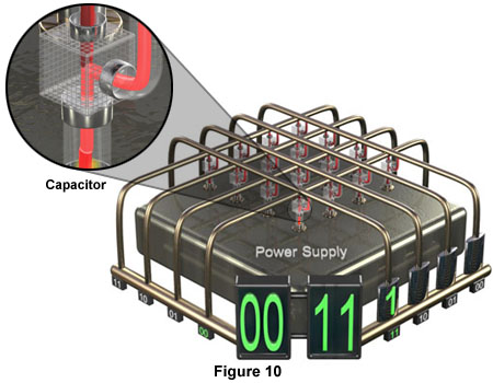
Computer MemoryIn most cases, the main memory of a computer is a high-speed random-access memory (RAM). Two types of main memory are possible with RAM circuits, static random-access memory (SRAM) and dynamic random-access memory (DRAM). A single memory chip is made up of several million memory cells. In a SRAM chip, each memory cell consists of a resistor circuit flip-flop for storing the binary digits 1 or 0. In a DRAM chip, each memory cell consists of a capacitor rather than a resistor circuit flip-flop. When a capacitor is electrically charged, it is said to store the binary digit 1, and when discharged, it represents 0. Figure 10 below shows a portion of a memory chip containing 16 memory cells.
A microphone converts sound waves into an electric signal. All microphones have a diaphragm that vibrates as sound waves strike. The vibrating diaphragm in turn causes an electrical component to create an output flow of current at a frequency proportional to the sound waves. A condenser microphone uses a capacitor for this purpose.
In a condenser microphone the diaphragm is the negatively charged plate of a charged capacitor. When a sound wave compresses the diaphragm, the diaphragm is moved closer to the positive plate. Decreasing the distance between the plates increases the electrostatic attraction between them. This results in a flow of current to the negative plate. As the diaphragm moves out in response to sound waves, the diaphragm moves further from the positive plate. Increasing the distance between the plates decreases the electrostatic attraction between them. This results in a flow of current back to the positive plate. These alternating flows of current provide weak electronic signals which travel to a mixer, then to an amplifier, and finally to a loudspeaker. You can observe the operation of a condenser microphone at our Condenser Microphone Java Tutorial.
| Interactive Java Tutorial | |||||||||||
|
|||||||||||
Variable capacitors are used in tuning circuits of radios. In Figure 11, a variable capacitor is connected to an antenna-transformer circuit. Transmitted radio waves cause an induced current to flow in the antenna through the primary coil to ground.
A secondary current in the opposite direction is induced in the secondary coil. This current flows to the capacitor. We know that the surge of current to the capacitor induces a counter electromotive force. This counter electromotive force is call reactance. The induced flow of current through the coil also induces a counter electromotive force. This is called inductive reactance. So we have both capacitive and inductive reactance.
At higher frequencies, inductive reactance is greater and capacitive reactance is smaller. At lower frequencies the opposite is true. A variable capacitor is used to equalize the inductive and capacitive reactances. The condition in which the reactances are equalized is called resonance. The particular frequency that is isolated by the equalized reactances is called the resonant frequency.
A radio circuit is tuned by adjusting the capacitance of a variable capacitor to equalize the inductive and capacitive reactance of the circuit for the desired resonant frequency, or in other words, to tune in the desired radio station. Our Radio Receiver Interactive Java Tutorial demonstrates how a variable capacitor is used to tune in radio frequencies.
| Interactive Java Tutorial | |||||||||||
|
|||||||||||
At the National High Magnetic Field Laboratory, magnets are used for research in all areas of science, including biology, chemistry, geology, engineering, material science, and physics. Research in high magnetic fields is critical because it allows scientists to study matter at the molecular level.
One type of magnet used is a pulsed magnet. Pulsed magnets are capable of inducing magnetic fields as high as 800 teslas. In order to generate such high fields, extremely high electrical currents are required, often in the tens of thousands of amps. Pulsed magnets are usually powered by a capacitor bank, a device containing a large number of capacitors capable of storing massive amounts of electrical energy. The capacitor bank is discharged in a fraction of a second through the coil of the magnet. Typical energies are of the order of 0.5 to 1 megajoules. We have simulated the powering of a pulsed magnet in our Pulsed Magnet Interactive Java Tutorial.
| Interactive Java Tutorial | |||||||||||
|
|||||||||||
Links to more information about pulsed magnets:
BACK TO ELECTRICITY AND MAGNETISM HOME