
Total Internal Reflection Fluorescence Microscopy
Interactive Tutorials
Evanescent Field Polarization and Intensity Profiles
Evanescent wave intensity at the interface surface (I(o)) is a function of both the incident angle and the polarization components of the light beam. The I(o) intensities observed for polarized vibration vectors are discussed in terms of a coordinate system with the plane of incidence (the x-z plane) defined as being parallel to the exciting light beam.
This tutorial explores how changes in the incident angle affect evanescent wave intensity and the relationships between the electric field vectors of parallel and perpendicular components of the incident beam.
The tutorial initializes with an single incident light ray (positioned at a 64 degree angle from the normal) undergoing total internal reflection at a glass/water interface having refractive indices of 1.518 and 1.333, respectively. Penetration of a portion of the incident light into the low refractive index medium creates the evanescent field, which is represented by several smaller light waves propagating parallel to the interface and having decreased intensity with increasing distance from the interface. The electric and magnetic field components of the evanescent waves are indicated by arrows or dots (perpendicular to the plane of the browser window) in the tutorial. Rotation of the tutorial about the z-axis is accomplished with the View Angle slider, which will enable up to a 90-degree change in viewing angle. The incident angle can be altered from a range of zero to 72 degrees with the Incident Angle slider. A pair of radio buttons is utilized to toggle between the incident light polarization directions, p and s, which invoke a corresponding change in the evanescent field polarization.
Two independent incident light polarization directions, termed p and s, are possible. These are electric field vectors parallel (p) and perpendicular (s) to the plane of incidence defined by the paths of the incident and reflected light beams. The evanescent electric field vector for the s-polarized incident light is perpendicular (or normal) to the plane of incidence. A non-zero longitudinal component and phase lag manifests the p-polarized incident light, which has an evanescent electric field vector direction that remains in the plane of incidence. The longitudinal component induces the p-polarized light electric field vector to "cartwheel" along the interface and produce elliptical polarization of the evanescent field in the plane of propagation. A spatial period of:
is observed for the p-polarized electric field vectors. The spatial period is not affected by the refractive index or dielectric properties of the resident medium (aqueous buffer or water). Instead, it is determined by the spacing of the incident light wavefronts in the glass medium as they intersect the interface. When the incident angle is reduced from the supercritical range to the critical angle and lower, the longitudinal component disappears and the electric field component in the x-direction simultaneously vanishes.
The evanescent field intensities at the interface (z = 0) for the incident p and s components are complex expressions given by the following series of equations:
where n represents the refractive index ratio (n(2)/n(1)), which is less than unity, and q is the incident angle. For s-polarized incident light, the total evanescent intensity is equal to the y-component, I(y), while the evanescent intensity for p-polarized incident light is composed of both the x and z components (I(x) and I(z)). As discussed above, the y intensity is linearly polarized, but the x and z intensities are elliptically polarized due to the fact that the electric fields are 90-degrees out of phase with each other.
The p and s evanescent intensities are illustrated in Figure 1 as a function of incident angle for transmitted light in the lower refractive index medium when passed through an interface composed of fused quartz (n(1) = 1.46) and water or an aqueous buffer solution (n(2) = 1.33). These calculations assume a condition of total internal reflection and require a critical angle of 65.7 degrees for the refractive indices listed. Intensity, plotted on the ordinate, is expressed as the ratio of evanescent intensity at the interface (z equals zero) to the incident intensity for each polarization angle. It is interesting to note that the evanescent intensities for both polarization orientations exhibit a range between one and five times that of the plane wavefront incident intensity for angles within 15 degrees of the critical angle.
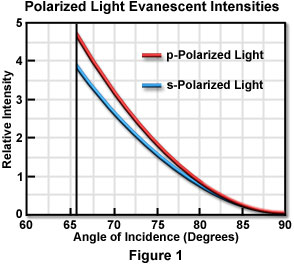
Although not illustrated in Figure 1, evanescent intensities of the polarized components can be extended (without breaks) to the subcritical angle region, which is good evidence for the continuity of the transition to total internal reflection. As the incident angle approaches 90 degrees, the evanescent intensities drop almost to zero.
Contributing Authors
Daniel Axelrod - Department of Biophysics, University of Michigan, 930 North University Ave., Ann Arbor, Michigan 48109.
John C. Long and Michael W. Davidson - National High Magnetic Field Laboratory, 1800 East Paul Dirac Dr., The Florida State University, Tallahassee, Florida, 32310.
BACK TO TIR FLUORESCENCE MICROSCOPY