
Interactive Java Tutorial
White and Black Balance
The color of digital images captured with an optical microscope is dependent not only upon the spectrum of visible light wavelengths transmitted through or reflected by the specimen, but also on the spectral content of the illuminator. In color digital camera systems that employ either charge-coupled device (CCD) or complementary metal oxide semiconductor (CMOS) image sensors, white and/or black balance (baseline) adjustment is often necessary in order to produce acceptable color quality in digital images.
The tutorial initializes with a randomly selected specimen image, captured in the MIC-D digital microscope, appearing in the left-hand window entitled Specimen Image. Each specimen name includes, in parentheses, an abbreviation designating the contrast mechanism employed in obtaining the image. The following nomenclature is used: (BF), brightfield; (DF), darkfield; (OB), oblique illumination; and (RL), reflected light. Visitors will note that specimens captured using the various techniques available with the MIC-D microscope behave differently during image processing in the tutorial.
Positioned adjacent to the Specimen Image window is the Balanced Image window, which displays the image after white or black balance correction algorithms have been applied to the specimen image. In order to operate the tutorial, select either the White Balance or Black Balance radio button from the Balance Mode listing at the bottom of the tutorial window. Next, choose Point Selection or Rectangular Selection from the Area Selection Method list. If Point Selection is chosen, position the mouse cursor over an area that should appear either white or black in the image and click on the button to apply the appropriate algorithm to the specimen image. The Balanced Image window will automatically display the processed image with either the white or black correction applied. Choosing the Rectangular Selection radio button will enable the marquee selection of a specific area in the image over which the correction algorithm will be applied.
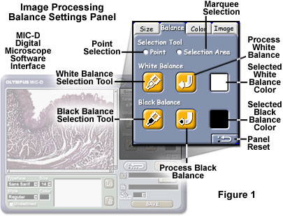
The Olympus MIC-D digital image processing software interface contains a Balance settings panel (see Figure 1) that enables the user to adjust both the white and black balance of images captured with the microscope. When the image processing software is launched and a digital image is loaded into the display window, selecting the Balance tab initializes the panel illustrated in Figure 1. The balance Selection Tool option can be utilized to define either a single pixel or marquee selection area by choosing the appropriate Point (single pixel) or Selection Area (marquee) radio button.
After the selection method has been enabled, the user should choose to correct either White Balance or Black Balance by clicking on the appropriate selection tool button (identified with either a white or black pen icon), which will be highlighted when the mouse cursor is hovering above. After clicking on the pen button, the mouse cursor can be moved over the image (simultaneously changing into a crosshair pattern) and the appropriate point (pixel) or rectangular area selected. If the Point tool is chosen, the area of interest should be placed in the center of the crosshair and the mouse button clicked once. Alternatively, if the Selection Area option is chosen, depress and hold the mouse button while dragging a rectangular selection area within the image window to define the region for balance correction. In order to obtain the best results, choose a light area of the background or a very prominent highlight region for white balance adjustment. Very dark or shadowed areas produce the best results when adjusting digital images for black balance.
After the balance target point or area has been selected, the single pixel or average pixel color to be corrected will appear in the far right-hand box entitled Selected Balance Color in Figure 1. To enable balance correction, click on the appropriate Process Balance arrow button (with either a white or black arrow) positioned between the pen tool button and the Selected Balance Color display box. At this point the software will apply the balance correction algorithm, and the results then appear as a modified image in the display window. The software can be reset to the original balance values by clicking on the Panel Reset button in the lower right-hand corner of the Balance Panel.
As discussed above, the color balance of a digital image is heavily influenced by the spectrum of wavelengths collected by the CCD or CMOS image sensor, regardless of whether the sensor is housed in a camera, telescope, laser bench, or microscope. In color digital cameras that employ these solid-state devices, a range of balance adjustments is often necessary in order to produce acceptable color images that conform to the color temperature of the illumination source.
The human eye is designed to readily adapt to changing illumination conditions in order to identify a white object as white even when the surrounding intensity and color temperature fluctuate. In contrast, digital cameras require careful scrutiny and adjustment of the red, green, and blue (RGB) signal amplitudes in order to produce similar results. A majority of digital cameras require measurement and adjustment of the color temperature to ensure that a white object is recorded as white, and to guarantee that other colors are also close to their acceptable limits. This process is often referred to as adjusting the white balance, and is a software and/or hardware option on many digital cameras.
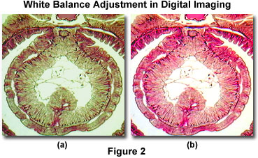
To exemplify the point, a typical example of color temperature (or color balance) errors in digital images captured with a microscope are presented in Figure 2. A brightfield image of Lumbricus terrestris (the common earthworm) was captured with the Olympus MIC-D digital microscope before and after adjusting the white balance look-up tables. Before adjusting the white balance setting (Figure 2(a)), the image has an overall green cast that softens the eosin and hematoxylin stain and masks the background color (which should appear white or a light neutral gray). After adjustment of the microscope's white balance look-up tables, the bright stain colors are devoid of any cast and reveal uniform distribution within the tissue (Figure 2(b)). In addition, the background has been shifted to a very light neutral color that is commonly observed when imaging specimens in brightfield illumination.
The specimen area should always be carefully selected for white balance measurement, because artifacts in the specimen can often lead to errors in the determination of white balance. On darker or highly colored specimens, the camera's black balance setting should be adjusted, if possible. Differences in refractive index for the specimen or the presence or absence of a cover glass can lead to spherical aberration, which can affect the measurement of white balance (although to a minimal degree). In addition, bleeding of biological stains can also induce color shifts in the mounting medium, leading to errors in white balance calibration. Whenever possible, use the marquee (Rectangular Selection) tool to choose the largest possible area for white balance determination. This enables the software to average white balance calculations over a greater number of pixels and will generate more acceptable results. In some cases, especially when only a single pixel is selected, the overall white or black balance determination can be compromised, leading to images that are not adjusted properly.
The best white balance correction is often achieved when a digital camera is pointed at a white card instead of a colored object, or the specimen is completely removed from the microscope stage to achieve an evenly illuminated background. Setting the white balance with a specimen in place may cause the images to acquire a color cast, which can seriously impair image contrast and result in colors that deviate from those of the object or specimen. In addition, images viewed in polarized light, differential interference contrast, fluorescence, or other contrast enhancing techniques can present more difficulty in color balance adjustment. This usually occurs when backgrounds assume a tint due to the optical configuration of the camera or microscope. For example, when a first-order retardation plate is inserted between the polarizer and analyzer in polarized light microscopy, the entire viewfield appears magenta, which makes white or black balance adjustment very difficult. A similar effect is observed in differential interference contrast microscopy. In many cases, the black balance value is much easier to establish, leading to much sharper images with jet black backgrounds and a significant improvement in overall image contrast.
Modern consumer and scientific CCD digital camera systems usually incorporate reference circuitry that contains a digital signal processor (DSP) circuit designed to electronically adjust the color balance of images recorded by the sensor. The processing circuitry provides a series of look-up tables, which are utilized by the software to adjust the red, green, and blue signals in order to arrive at the proper color balance for a specific illumination intensity and color temperature. Often, the look-up tables will contain information about tungsten-halogen (at a variety of color temperatures) lamps, mercury and xenon arc-discharge burners, flash tubes, light emitting diodes, among other common illumination sources. The RGB system is one of the primary color models utilized to specify and represent colors in computer-controlled cameras and software. White is produced by combining equal parts of all three colors (red, green, and blue) at levels of 100 percent. Adjustments for color temperature can easily be made by adjusting the intensity level of one or more of these primary colors.
In addition to the camera system, the computer or video monitor utilized to view images often requires a corresponding adjustment for color temperature in order to match color information collected by the digital camera. Many computer software packages contain a white point algorithm that enables adjustment of the software to match color temperature, but the hardware must often be adjusted as well. Computer monitors usually have external adjustments that allow the user to toggle between several choices of color temperature, ranging from about 9000 K down to 5000 K. These settings can be changed to match standard viewing conditions and to ensure that the image seen on the screen truly represents the one captured by the camera.
Contributing Authors
Kenneth R. Spring - Scientific Consultant, Lusby, Maryland, 20657.
John C. Russ - Materials Science and Engineering Department, North Carolina State University, Raleigh, North Carolina, 27695.
Matthew J. Parry-Hill and Michael W. Davidson - National High Magnetic Field Laboratory, 1800 East Paul Dirac Dr., The Florida State University, Tallahassee, Florida, 32310.
BACK TO DIGITAL IMAGE CAPTURE AND PROCESSING
BACK TO THE OLYMPUS MIC-D DIGITAL MICROSCOPE
Questions or comments? Send us an email.
© 1995-2022 by Michael W. Davidson and The Florida State University. All Rights Reserved. No images, graphics, software, scripts, or applets may be reproduced or used in any manner without permission from the copyright holders. Use of this website means you agree to all of the Legal Terms and Conditions set forth by the owners.
This website is maintained by our
Graphics & Web Programming Team
in collaboration with Optical Microscopy at the
National High Magnetic Field Laboratory.
Last Modification Wednesday, Jan 11, 2017 at 11:55 AM
Access Count Since September 17, 2002: 19911
Visit the website of our partner in introductory microscopy education:
|
|