
Fluorescence Microscopy Interactive Tutorials
Reflected Light Fluorescence Microscopy Light Pathways
In reflected light Köhler illumination for fluorescence microscopy, an image of the light source is focused by the collector lens onto the aperture iris diaphragm located in the vertical illuminator. This diaphragm shares a conjugate plane with the rear aperture of the objective and the lamp arc or filament, and therefore, determines the illuminated field aperture size. Together, the light source, vertical illuminator aperture diaphragm, and objective rear focal plane (pupil) form the illumination set of conjugate planes. Opening or closing the aperture diaphragm is used to control stray light and regulate the intensity (numerical aperture) of illumination without altering the size of the illuminated field. In the image, adjustment of the aperture diaphragm affects brightness and contrast. This interactive tutorial explores the light pathways in a reflected light (episcopic) fluorescence microscope.
The tutorial initializes with a cut-away schematic diagram of a reflected light fluorescence microscope appearing in the window. Clicking on the Outside button will revert the image to an external view of the microscope (and change the button to read Inside). In order to operate the tutorial, use the Field Diaphragm and Aperture Diaphragm sliders to adjust the field size and numerical aperture, respectively, of the microscope illumination. The Illumination Intensity slider varies the output from the virtual lamphouse between arbitrary values of 25 and 100 percent. Fluorescence filter blocks housed in the vertical illuminator turret can be changed using the Filter Cube slider. The excitation wavelengths available in the tutorial are 350, 450, 550, 600, and 650 nanometers. As the filter blocks are rotated into the light path, the illumination color changes to match excitation and fluorescence emission wavelengths of the individual filter sets.
The image-forming or field set of conjugate planes in reflected light Köhler illumination consists of the field diaphragm, the specimen surface, and the intermediate image plane. Thus, when the field diaphragm is placed in focus at the specimen plane, the image of the light source is significantly removed from focus in order to provide a uniform field of illumination. The field diaphragm controls the size of the illuminated field without affecting the illumination intensity of the area being observed. In practice, the field diaphragm opening size should be as small as possible in order to increase image contrast and to reduce the degree of photobleaching in areas not being directly observed. Köhler illumination produces even illumination of the specimen field in spite of the uneven illumination intensity generated by most arc-discharge and filament-based light sources. When the microscope is properly configured, the rear focal plane of the objective is fully illuminated, providing a field that is uniformly bright from edge to edge. Köhler illumination, in the ideal case, bathes the specimen with a converging set of wavefronts, each arising from separate points on the light source imaged into the condenser aperture. In a properly configured fluorescence microscope, the result is optimum image contrast and resolution.
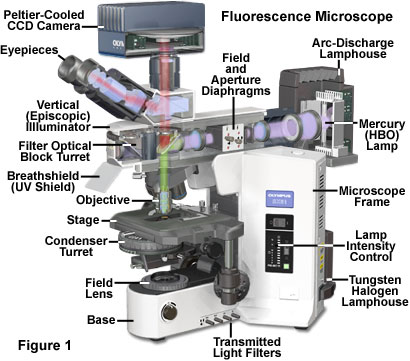
Reflected light fluorescence microscopy is overwhelmingly the current method of choice for widefield investigations with non-coherent light sources, as well as those conducted with laser scanning confocal and multiphoton instruments. This popular mode of fluorescence microscopy is also known as incident light fluorescence, episcopic fluorescence, or simply epi-fluorescence. A typical modern reflected light fluorescence microscope, also equipped for transmitted light observation in a variety of contrast-enhancing modes, is presented in Figure 1. The microscope contains a trinocular observation head that is coupled to a charge-coupled device (CCD) camera system, and has two illumination sources, one for transmitted light and the other for episcopic observations (tungsten-halogen and mercury arc-discharge, respectively). A microscope of this design can combine or alternate reflected light fluorescence with transmitted light phase contrast, differential interference contrast (DIC), polarized light, or Hoffman modulation contrast observation.
The essential feature of any fluorescence microscope is to provide a mechanism for excitation of the specimen with selectively filtered illumination followed by isolation of the much weaker fluorescence emission using a second filter to enable image formation on a dark background with maximum sensitivity. Localized probe concentration in biological specimens is so low in many experiments that only a small fraction of the excitation light is absorbed by the fluorescent species. Furthermore, of those fluorophores that are able to absorb a quantity of illumination, the percentage that will emit secondary fluorescence is even lower. The resulting fluorescence emission brightness level will range between three and six orders of magnitude less than that of the illumination. Thus, the fundamental problem in fluorescence microscopy is to produce high-efficiency illumination of the specimen, while simultaneously capturing weak fluorescence emission that is effectively separated from the much more intense illumination band. These conditions are satisfied in modern fluorescence instruments by a combination of filters that coordinate excitation and emission requirements based on the action and properties of the dichromatic beamsplitter.
Contributing Authors
Mortimer Abramowitz - Olympus America, Inc., Two Corporate Center Drive., Melville, New York, 11747.
Matthew J. Parry-Hill and Michael W. Davidson - National High Magnetic Field Laboratory, 1800 East Paul Dirac Dr., The Florida State University, Tallahassee, Florida, 32310.
BACK TO FLUORESCENCE MICROSCOPE ANATOMY
BACK TO FLUORESCENCE MICROSCOPY