
Differential Interference Contrast
Interactive Tutorials
Optical Sectioning in Reflected Light DIC
The ability to capitalize on large objective numerical aperture values in reflected light DIC microscopy enables the creation of optical sections from a focused image that are remarkably shallow. Without the confusing and distracting intensity fluctuations from bright regions occurring in optical planes removed from the focal point, the technique yields sharp images that are neatly sliced from a complex three-dimensional opaque specimen having significant surface relief. This property is often employed to obtain crisp optical sections of individual features on the surface of integrated circuits, as explored in the interactive tutorial, with minimal interference from obscuring structures above and below the focal plane.
The tutorial initializes with a randomly selected integrated circuit image appearing in the DIC Specimen Image window and a model of an objective and the surface of a wafer on the right-hand side of the window. In order to operate the tutorial, use the Objective Focus slider to focus the specimen through a range of planes starting at the upper surface and progressing through the central region to the lower surface. As the slider is translated, various image planes in the specimen will be brought into sharp focus. Simultaneously, the microscope objective model will move upward and downward with respect to the wafer surface to simulate the actual relationship in the microscope. A new integrated circuit can be examined by selecting from the palette in the Choose A Specimen pull-down menu.
In reflected light microscopy, the vertical illuminator aperture diaphragm plays a major role in defining image contrast and resolution. Reducing the aperture size increases the apparent depth of field and overall image sharpness while simultaneously producing enhanced contrast. However, if the diaphragm is closed too far, diffraction artifacts become apparent, image intensity is significantly reduced, and resolution is sacrificed. Often, the optimum aperture diaphragm setting is a compromise between accurately rendering specimen detail in sufficient contrast and retaining the resolution necessary to image minute features, while at the same time avoiding diffraction artifacts.
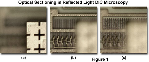
The series of high-magnification DIC images presented in Figure 1 illustrate three separate focal planes in the same viewfield of overlapping surface structures present on a typical integrated circuit. In brightfield or darkfield illumination, these structures are often observed merged together and can become quite confusing when attempting to image specific surface details. Figure 1(a) reveals several mask alignment targets on a metal bonding pad near the upper surface of the integrated circuit. Refocusing the microscope a few tenths of a micrometer deeper exposes numerous connections in the central region of the circuit (Figure 1(b)). Still farther into the circuitry (Figure 1(c), adjacent to the first layers applied above the pure silicon, are a series of metal oxide lines dotted with an ordered array of via connections. The optical sectioning capability of reflected light DIC microscopy is clearly revealed by the ability to image specific focal planes on the surface of this complex integrated circuit.
Contributing Authors
Matthew Parry-Hill and Michael W. Davidson - National High Magnetic Field Laboratory, 1800 East Paul Dirac Dr., The Florida State University, Tallahassee, Florida, 32310.
BACK TO DIFFERENTIAL INTERFERENCE CONTRAST