
QX3 Microscope Body
The Intel QX3 Computer Microscope body contains the digital imaging electronics, the objectives, an incandescent tungsten reflected light illuminaton source, and provides power to the stand for transmitted light illumination. A USB cable and connector attached to the digital imaging circuit board provides an interface to the computer and draws power from the 3.3 and 5.0 volt DC sources in the power supply to power the imaging electronics and the illuminators.
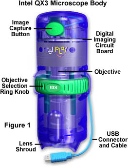
Figure 1 illustrates the major components of the microscope body. The large green button at the top of the body is the digital image capture button. This button is pressed to acquire an image when the microscope is operated in the hand-held standalone mode, separated from the stand. Digital movies can also be made by pressing the image capture button and holding it down. While the button is depressed, the QX3 Live View screen captures video at the rate of 12 frames/second. When the button is released, the software ceases recording and saves the images on the computer's hard drive as an *.AVI file. The cable connecting the microscope body to the USB port at the rear of the computer is eight feet long, which somewhat restricts the useful region for imaging with the microscope body. Regardless of this limitation, there are a wide variety of specimens that can be brought withing range of the body for magnification and imaging.
There is a blue shroud (illustrated in Figures 2 and 3), which protects the objective lens cover and illuminator diffusion screen from impact during standalone use of the body (Figure 2). The shroud also provides a convenient guide to objective working distance (the distance from the front lens of the objective to the specimen) while imaging specimens in the hand-held mode. At low magnifications (10x and 60x), most specimens will be in focus when the shroud is rested on a stable surface. Using a solid surface to stabilize the body is necessary for capturing single frame digital images that are not blurred or out of focus due to movement of the body while acquiring the image.
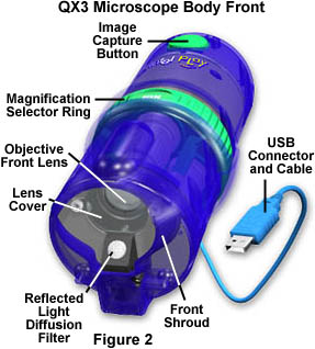
The large green magnification selection ring in the center of the body is used to interchange the microscope's objectives. Turning the ring to the right moves the next higher magnification objective into the optical path. The objectives are arranged sequentially so turning the selection ring to the right installs the 10x, 60x, and 200x objectives in that order. Specimens should always be first imaged with the lowest magnification 10x objective to establish the correct working distance for the microscope. A stainless steel ball bearing detenté is used to secure each objective into the light path. Students can hear and feel the detenté clicking into position as the objectives are changed, which provides positive feedback that the objective is correctly inserted into the optical path.
The reflected light tungsten lamp is turned on by the software when the microscope body is removed from the stand. This lamp is the sole source of illumination (with the exception of the surrounding room light) when imaging specimens in the hand-held mode. Additional illumination can be obtained from a flashlight or desk lamp positioned to illuminate the specimen from above. The protective shroud acts to shield a significant amount of incoming light from the sides of the microscope, but the front of the body is open to accept light from auxiliary sources.
When using the microscope body in the standalone mode, be careful to protect the lens cover from collisions and contamination with dirt, water, solvents, or other foreign materials. Maintaining a clean and scratch-free lens cover is a key to obtaining high quality images with the QX3 microscope. If the cover becomes dirty, use a lint-free cloth dampened with window cleaner to carefully wipe it clean.

A cutaway diagram of the QX3 microscope body is illustrated in Figure 3. Visible in the diagram are the digital imaging circuit board, a small box containing a dichroic window that acts as an infrared cutoff filter, the microscope objective barrels, and some details about the magnification selection turret. CMOS active pixel sensor imaging chips are particularly sensitive to infrared light, which can cause a number of problems when using these chips for imaging in the visible wavelength region. The cutoff filter protects the CMOS integrated circuit from excess infrared electromagnetic radiation and helps balance visible light entering the sensor.
The stainless steel bearing objective alignment detenté is housed on the upper of two plastic plates that are positioned between the back aperture of the objective and the cutoff filter box. As the magnification ring turret is rotated, the detenté captures the objective and positions it directly in the optical pathway with the objective back aperture in line with the cutoff window and the front lens correctly aligned with the lens cover.
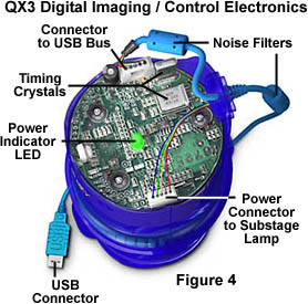
The digital imaging and microscope control electronics circuit board is illustrated in Figure 4. The blue USB connector is attached to a cable of the same color and plugs into a port at the back of the host Windows 98 computer. As we mentioned above, the length of the cable is eight feet, so the microscope can be used a short distance from the computer, but it is impossible to control the software when out of reach of the keyboard and mouse.
Inside the body, the USB cable attaches to a connector on the control electronics circuit board. The USB connection is the input/output port for electrical power and communications between the microscope and the computer. A green power-indicating light emitting diode (LED) lights when communications are established with the computer and remains on throughout the lifetime of the communication link.
Another connector on the circuit board controls power to the substage tungsten lamp through a set of contacts on the microscope body that meet corresponding contacts on the stand. When the body is removed from the stand, the connection between the body and stand contacts is broken and the microscope switches on the tungsten lamp in the body (even if the stage lamp was in use when the body is removed). The Live View software window contains controls to activate the body and stage lamps and to switch between the two.
The digital imaging electronics are thoroughly discussed in a separate section. Other support electronics on the circuit board include timing circuits, a BIOS chip, the switch for the image capture button, and various minor components that assist in communications with the computer and operation of the microscope.
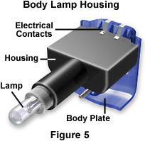
The lamp housing for the microscope body tungsten lamp is illustrated in Figure 5. This housing is attached to the body with a single Phillips-head screw and is easily removed to replace the lamp. When replacing the lamp, remember to avoid touching the glass bulb with bare hands. Always use a tissue paper to remove and replace the lamp to avoid contamination by protein, salts, and oils from the fingerprints. If the glass bulb is accidently touched, moisten a tissue paper with a small quanity of window cleaner and wipe the bulb clean. Replacement lamps are available through phone numbers in the owner's manual or at the Mattel website.
BACK TO INTEL PLAY QX3 MICROSCOPE ANATOMY
Questions or comments? Send us an email.
© 1995-2025 by Michael W. Davidson and The Florida State University. All Rights Reserved. No images, graphics, software, scripts, or applets may be reproduced or used in any manner without permission from the copyright holders. Use of this website means you agree to all of the Legal Terms and Conditions set forth by the owners.
This website is maintained by our
Graphics & Web Programming Team
in collaboration with Optical Microscopy at the
National High Magnetic Field Laboratory.
The QX3 microscope design is copyrighted © 2025 by Mattel, Inc. Intel® Play™ is a registered trademark of the Intel Corporation. These companies reserve all of their rights and privileges under copyright law. The material contained in this website is solely the opinion of the authors and is intended for eduational use only.
Last Modification Friday, Nov 13, 2015 at 02:18 PM
Access Count Since December 24, 1999: 37510
Visit the official Intel Play website:
![]()