
Objective Design and Architecture
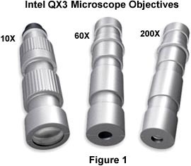
The Intel Play QX3 computer microscope is capable of examining specimens at three magnifications through the use of individual objectives that have magnification powers of approximately 10X, 60X, and 200X. The barrels of these objectives are constructed out of an injection-molded polymer (probably acrylonitrile-butadiene-styrene or ABS) and have plastic lenses fabricated from polymethylmethacrylate (PMMA) strategically positioned to optimize their performance.
The diameter of the light beam passing through each objective is controlled by an aperture molded into the polymer barrel. By using apertures that restrict light pathways to the center of the lenses, spherical aberration is reduced in the objectives leading to the production of better images. The objectives are molded in two pieces that are fitted together with locator tabs to ensure proper positioning of the internal lenses. The 10X objective contains two lenses (see Figure 2): a front lens that is convex on the object side and concave on the image side of the lens, and a plano-convex lens that projects the image into the CMOS Active Pixel Sensor integrated circuit located on the image-capture circuit board.
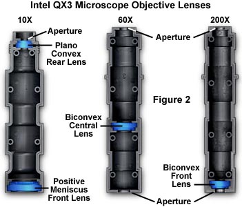
Also illustrated in Figure 2 are the 60X and 200X objectives that each contain a single lens element. The 60X objective has apertures at both the front and rear of the barrel to limit the path of light entering the objective to the central portion of the lens element, which is located near the front center of the objective. The 200X objective has a double convex lens near the smaller front aperture and a rear aperture similar in size to the 60X objective. All three objectives suffer from optical aberrations, but the use of a single lens in the higher power objectives acts to reduce this unwanted effect. Lens elements each have a flat section on the edge that matches an identical flat in the mounting housing of the objective barrel. This ensures that the lenses are positioned properly within the barrel.
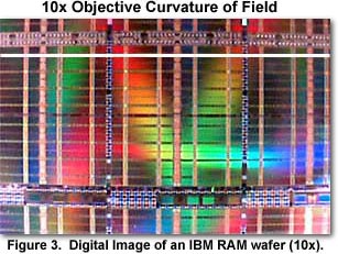
The most pronounced aberration in these objectives is curvature of field, illustrated in Figure 3 with a digital image of the surface of a wafer containing 16 Megabit dynamic RAM chips. A white horizontal line has been drawn across the image to demonstrate curvature of the scribe lines dividing individual chips. It is clear that the distance between the scribe line and the white horizontal line is greatest in the center of the image and decreases towards the edges. The field curvature effect is most pronounced in the lowest power 10x objective, but is present to a certain degree in all three objectives. Specimens that have irregular structures and features also are affected by field curvature, however the aberration is not as obvious in digital images of these specimens due to the lack of straight edges.
In addition to helping cope with spherical aberration, the restricted size of the objective apertures also increase the apparent flatness of field in the higher power objectives and minimize the effects of minor aberrations such as coma and astigmatism. The objectives are designed to have approximately the same working distance, which we have measured to be between 25 and 28 millimeters. This allows quick changes in magnification without requiring large movements of the stage. The microscope body can also be removed from the stand and used as a stand-alone microscope to image specimens that will not fit on the stage.
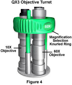
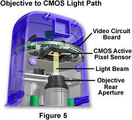
All three objectives are mounted into a turret (or lock cylinder, illustrated in Figure 4) that is used to accurately position a selected objective in the microscope optical axis or light path. Precise positioning is achieved by the use of a stainless steel ball-bearing that is used as a détente to lock the turret into place. Objective magnifications are stamped onto a green plastic knurled selector ring that allows rotation of the turret. When properly positioned the light path, an objective is directly in the center of the frosted diffusion screen on the stage and also aligned to project an image of the specimen onto the Active Pixel Sensor CMOS chip (as illustrated in Figure 5).
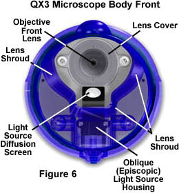
A clear polycarbonate lens cover (illustrated in Figure 6) protects the front lenses of the objectives. The lens cover is secured into place on the body face of the microscope by means of two Phillips-head screws. With use, the lens cover can become contaminated with oil, dirt, fingerprints, and other debris that should be removed with compressed air. Intel and Mattel recommend that lens cleaners, abrasive tissue, and brushes should not be used to clean the lens cover. Our studies indicate that this cover is easily scratched and we suggest great care in cleaning this protective cover to minimize artifacts in imaging specimens. Replacements can be obtained by contacting Mattel Consumer Affairs using a toll-free number that is listed in the owner's manual. It is probably a good idea to buy several replacement covers so one will be on hand in case of an emergency.
Surrounding the front lens cover is a protective shroud that doubles as a spacer when the microscope body is removed from the stand and held close to a remote object for imaging. The shroud ensures that large specimens can approach no closer than 2 centimeters from the lens cover, which is the approximate working distance of the objectives. In this manner, the shroud serves as a guide to the proximity of the microscope body with respect to the specimen when used without a stand.
In conclusion, the Intel QX3 microscope has three plastic objectives ranging in magnification from 10X to 200X. Although the lenses are formed from a clear polycarbonate injection-molded plastic, they perform amazingly well for their simplicity. Imaging problems with this microscope arise from relatively poor performance of the objectives coupled to random noise problems generated by amplifiers in the active pixel sensor CMOS image-capture chip. When compared to low-end optical microscopes in the $500-$1500 range, the QX3 produces images that are less sharp and color saturated and are generally lacking in overall specimen resolution and detail. Reduced image quality can often be overlooked when the microscope is to be used as a teaching tool because of the unique digital imaging features and advanced software interface.
BACK TO INTEL PLAY QX3 MICROSCOPE ANATOMY
Questions or comments? Send us an email.
© 1995-2025 by Michael W. Davidson and The Florida State University. All Rights Reserved. No images, graphics, software, scripts, or applets may be reproduced or used in any manner without permission from the copyright holders. Use of this website means you agree to all of the Legal Terms and Conditions set forth by the owners.
This website is maintained by our
Graphics & Web Programming Team
in collaboration with Optical Microscopy at the
National High Magnetic Field Laboratory.
The QX3 microscope design is copyrighted © 2025 by Mattel, Inc. Intel® Play™ is a registered trademark of the Intel Corporation. These companies reserve all of their rights and privileges under copyright law. The material contained in this website is solely the opinion of the authors and is intended for eduational use only.
Last Modification Friday, Nov 13, 2015 at 02:18 PM
Access Count Since October 27, 1999: 42011
Visit the official Intel Play website:
![]()